benlong


MCB Injection Mold Development Process: From Design to Mass Production
By Huang Xiaolei | Release Time: 2026-06-26
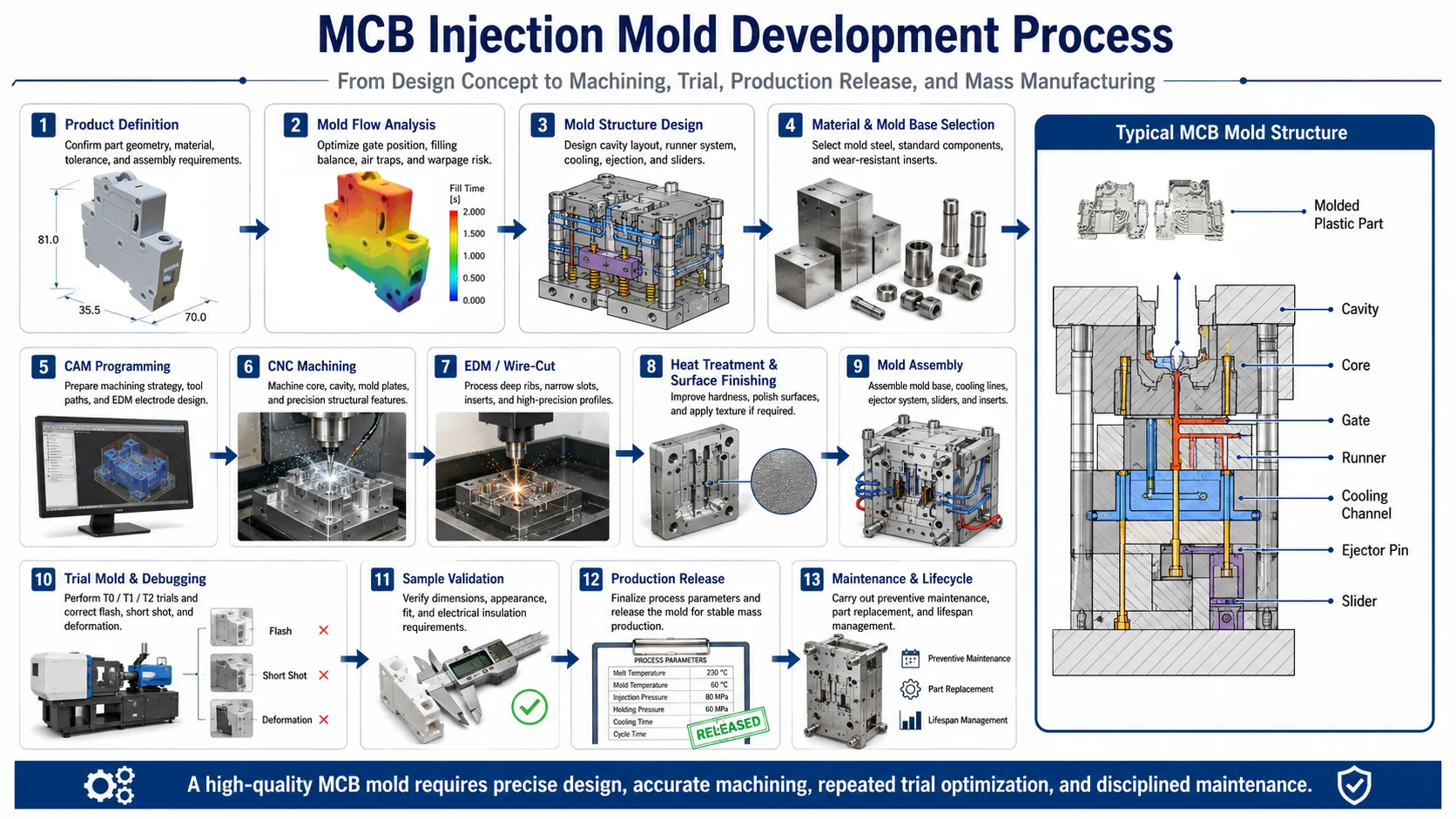
An MCB injection mold is specifically designed for producing a vast number of similar miniature circuit breaker cases with precision control of tolerances throughout the production process. The reality of this statement does not appear until one considers the underlying tool. The MCB injection mold is made from a special type of heat-treated steel (hardened steel), and has been engineered for use in over one million cycles and must maintain core and cavity dimension tolerances of ±0.005–0.01 mm, and have a polished finish that approaches a mirror-like finish on all external surfaces. Conformance to these requirements requires a disciplined sequence of design, simulation, machining, and testing; as a result, skipping any phase of this process will result in problems with flash, short shots, or circuit breaker housings not mating together during assembly. This article discusses the complete development process from a preliminary design review of the circuit breaker housing until the MCB injection mold is ready for full mass production.
What Defines a High-Precision MCB Injection Mold
Before getting into the workflow, it helps to know what “good” looks like for this kind of tool. MCB housings — the case, cover and handle — are small, thin-walled parts with snap-fit features and tight assembly relationships, so the mold has to hold dimensions closely and repeat them shot after shot. A few benchmarks most projects aim for:
- Service life of no less than 1 million cycles for the molding components.
- Machining accuracy of ±0.005–0.01 mm on the core, cavity and critical inserts.
- High-gloss or mirror polish on visible surfaces, which improves both part appearance and demolding.
- Cavity and core hardness around 48–52 HRC after vacuum heat treatment, for wear resistance and dimensional stability over the tool’s life.
Hit those four and the mold runs cleanly. Miss them and you pay for it in scrap and downtime.
Product Definition and Mold Flow Analysis
The initial step in every project is actually the part, not the mold. The 3D Model of the housing, selected plastic, tolerance band, and appearance requirements are evaluated by the toolmaker with a special emphasis on how the case, cover and handle will fit together. This early stage of the project requires particular emphasis on the wall thickness distribution and snap-fit geometry because they will determine if the part can be manufactured without sink marks or warpage during the molding process.
After the requirements are finalized, the design is analyzed for mold flow. At this point, optimization occurs for gate locations, fill balances, weld line positions, air trap risks and warpage on-screen before the first piece of steel is machined. Having a multi-cavity, MCB mold requires balancing cavities, as it directly affects part-to-part consistency as well as production speeds of the tool on the shop floor.
Mold Structure Design
Once we have the results of our simulations, we can begin to lay out the full architecture of our tool. This includes defining the number of cavities and the layout of those cavities; designing the runner system; designing the cooling channels; creating an ejection mechanism(s); designing a slider and/or insert(s); etc.
The single largest driver for making these decisions is usually the production target. A program that requires millions of parts annually justifies building a mult-cavity, fully hardened, long-life mold. Although this type of mold costs more upfront, it allows for a per part cost reduction and consistent quality over an extended production run.
In terms of part quality, two features of this configuration offer great value considering their size: cooling layout, and venting.
Cooling channels can only pull heat from the cavity consistently, as uneven cooling is a frequent cause of warpage and dimensional shift, particularly in thin wall housings. Additionally, since a cooled part cannot be ejected until solidified adequately to retain its shape, it will set the benchmark for cycle time.
As with small MCB Parts, venting carries the same amount of significance. As the melt fills the cavity, it forces air out, and if there is no place for it to escape it will create short shots at the last to fill, burn marks, or gas porosity due to trapped air. Properly manufactured MCB molds have vents on the parting line, on the points where the melt has finished filling, and often vent the ejector pins.
Choosing the Right Mold Steel
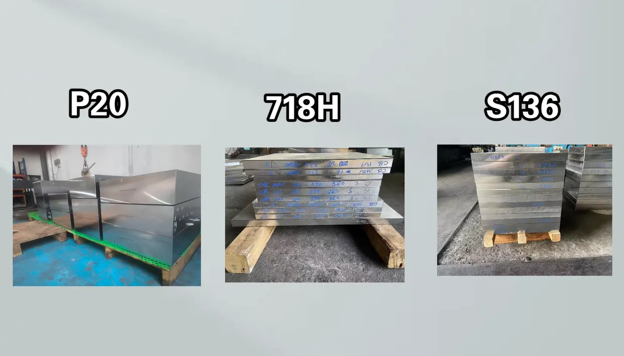
A lot of an MCB mold’s long-term performance is decided here, and different components call for different steels rather than one grade throughout:
each suited to a different component.
- P20 — a pre-hardened steel (roughly 28–32 HRC) that machines well and is economical, commonly used for mold bases and plates that don’t need high hardness.
- 718H — an improved pre-hardened grade with better internal uniformity and polishability than P20, a sound middle ground for larger plates and moderate-life cavities.
- S136 — a corrosion-resistant stainless mold steel that hardens to about 48–52 HRC after vacuum heat treatment, which makes it the usual choice for the cavity, core and critical inserts on high-gloss, long-life MCB molds.
Hardened materials, such as S136 tool steel (or similar grade for hot working like H13), provide the best option for the mold faces of high-volume tools or tool steels that are being used to process glass-filled or other abrasive materials. The decision to harden the faces depends on the cost of hardening and the lead time associated with using hardened faces compared to how long you can expect to get out of the mold. However, when using an MCB program with over 1 million cycles, the cost associated with the hardened route will typically pay for itself.
CAM Programming and Precision Machining
Process engineers are responsible for designing the machining sequence of each individual component before any metal is cut. This includes rough machining, semi-finish machining, finishing, EDM electrode design, and wire-cut programming. All of this solid CAM work lays the groundwork for quick and accurate subsequent stages.
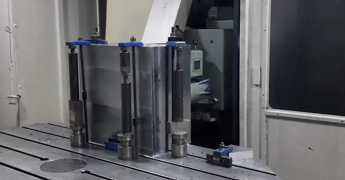
There are several separate processes involved in the cutting process. For example, CNC machining operates to create pieces for both the mold base and all cavity plates, as well as some other structural elements that can be machined with a conventional tooling system.
EDM and wire-cut take over where milling cutters can’t go cleanly — deep ribs, narrow slots, sharp inner corners, and the precision profiles on inserts. These are exactly the features that give an MCB housing its internal walls and locating detail, so the accuracy of this step carries straight through to the finished part.
After and before being machined, the molding parts are heat treater to their desired hardness and then surface polished to get the desired surface finish. It’s from that process, along with putting polish on the cavity surface, that the final housing will have a shine to it.
Assembly, Trial and Debugging
After all the parts have been created, it is time to assemble everything together to create a complete tool; i.e., the mold base, ejector system, cooling lines, inserts/guides and side-actions. The mold is then put onto a machine for testing usually before it can go into production (e.g., Type 0, Type 1 and Type 2).
Trial rounds are based on the identification and resolution of issues within the molds being tested. Engineers will assess fill quality, dimensional accuracy, demolding performance and cycle performance then deal with whatever appears during the test or trial process. For example, this can be excess flash (or sprue), short fill, deformation, or an imbalance in cavity distribution. Generally, several rounds of testing are required before items produced are usable for validation.
Sample Validation and Production Release
The samples will undergo official validation for dimensions, appearance, fit and the relationship of the molded case, cover and handle as part of the complete assembly. Once all samples pass their validation testing, the mold will then move to the production release phase in which all molding process parameter(s) will be established or locked-in; i.e., melt temperature, mold temperature, injection pressure, hold pressure, cooling time and total cycle time.
These parameters each play an important role within a specific step of the overall process of producing the shot (i.e. shot stage). The injection process injects molten resin into the cavity; packing pressure provides additional material to offset the shrinkage of the plastic during cooling; holding pressure keeps the cavity pressurised until the gate freezes shut, and therefore creates the final dimensional and weight characteristics of the part; and cooling until the part is sufficiently rigid to be removed from the mould. If there is an inadequate balance of the process parameters during any of these stages, the part will have identifiable defects (e.g. if there is an inadequate pack-and-hold, the part will have sink marks or will be underweight; if the pack-and-hold pressure is too high, the mould halves will interpolate and create flash at the parting line).
These parameters need to be determined through accurate data rather than guesswork, if you want to produce an injection-moulded product that can be relied upon for millions of cycles. A scientific moulding method – using cavity pressure sensors and structured testing (DOE) for each of the many variables of the plastic injection moulding process – produces a process window that can consistently replicate for every mould cycle; therefore, providing an essential requirement to producing a stable high volume of MCBs. Those finalized settings then carry the housings straight into downstream operations such as an MCB automatic assembly line, where consistent part dimensions are what keep the line running without jams.
Mold Maintenance and Lifecycle Management
Once an MCB mold is delivered it requires continued attention to maintain accuracy for over a million cycles, including preventing maintenance (cleaning, lubricating and inspecting wear parts) as well as replacing components before failure occurs. A well maintained mold produces consistent quality products for many years while a poorly maintained mold will drift out of tolerance and produce scrap long before expected.
A mold that creates parts is created with a precisely designed mold, accurately machined, thoroughly tested through the course of a trial (patience), and maintained with discipline over the course of its entire service. These factors all combine to create an identical product with the same quality as long as the same processes are followed.
Frequently Asked Questions
What steel is used for MCB injection molds?
The type of component determines the type of steel that can be used. Cavity inserts, core inserts and critical inserts usually use pre-hardened steel such as P20 or 718H, which will provide a flat, polished surface and a hardness of 48 – 52 HRC. For those who require high volume or use glass-filled material, Hot work grade H13 may be used on the molding faces.
How long does an MCB injection mold last?
Typical high-quality MCB tooling is engineered to last no less than 1,000,000 cycles of use within an average working environment; however, with proper construction and care, many tools have performed significantly beyond this minimum expected service life. The actual service life will be determined by the type of steel used in the manufacture of the tool, its choice of molded material, the tooling cycle parameters and the consistency of maintenance that has been performed on the tool over time.
How many cavities should an MCB mold have?
This is based primarily on the target production level per year and the complexity of the part. Higher production volumes will warrant the use of multi-cavity molds due to the desire to reduce per unit cost, however, there is an increase in difficulty in being able to control fill balance and balance between cavities as you add more cavities. This is why prior to finalizing the layout of the mold of the part, a mold filling analysis is performed.
Why is mold flow analysis important for MCB molds?
Before cutting the steel, engineers can use software to optimise the gate location, filling balance, weld lines, air traps and warpage.
In the case of multi-cavity tools, this is the primary means of keeping the balance of cavities and the consistency of parts, thus preventing expensive rework after the mold has been created.
What causes flash and short shots during mold trials?
Short Shots: Flash usually indicates a lack of adequate clamping force, wear on the parting line, or excessive injection pressure; short shots are caused by inadequate fill, low melt temperature, or trapped air and poor venting. Both flash and short shots are common results of trials (T0-T2) and correcting these issues will happen by altering or adjusting machine settings, tooling and/or process parameters prior to production runs.
How long does it take to develop an MCB injection mold?
The amount of time it takes to complete a high-precision multi-cavity MCB mold generally varies between a few weeks to several months after reaching the final design stage and before being put into production, depending on the complexity of the part being molded (or molded), number of cavities required, and number of trials to produce part. By utilizing mold flow analysis, along with a disciplined approach to trial prep (trials before manufacturing), those timelines can be minimized.
References
- Uddeholm — Mold Steels (incl. S136 / Stavax) — material data on stainless and pre-hardened mold steels used in injection tooling.
- Injection Moulding — Overview — background on the injection molding process, gating, cooling and defects.
- PlasticsToday — industry coverage of injection molding processing and tooling practice.
Conclusion
A well-built MCB injection mold is the quiet foundation under a high-volume breaker line: get the tool right and everything downstream runs cleaner, faster and with fewer rejects. The payoff comes from doing the unglamorous work well — defining the part properly, simulating before cutting, choosing the right steel for each component, machining to tolerance, trialing patiently, and maintaining the mold once it’s in production. For manufacturers building breakers at scale, that discipline is what turns a mold from a one-off tool into a dependable production asset. If you’re planning the downstream side of the line as well, see how molded housings flow into an MCB automatic assembly line, and our guide to choosing an MCCB contact welding machine for related circuit-breaker manufacturing equipment.