Benlong


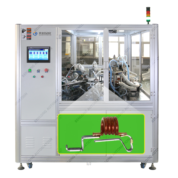
RCBO PCBA automatische Lötmaschine
Kundenspezifische RCBO-PCBA-Lötmaschine für 17,8 mm ±0,08 mm Module. 3-Linien-Parallellöten, Schnellwechselwerkzeug, Positionserkennung. Inline-Prozess: Trennung → Verteilung → Station A (3 Positionen) → Zusammenführung → Station B. Angepasst an Ihr PCBA-Layout. Hoher Durchsatz, geringe Fehlerquote.
Automatische Inline-Lötmaschine für RCBO PCBA
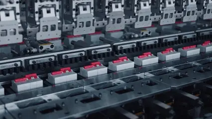
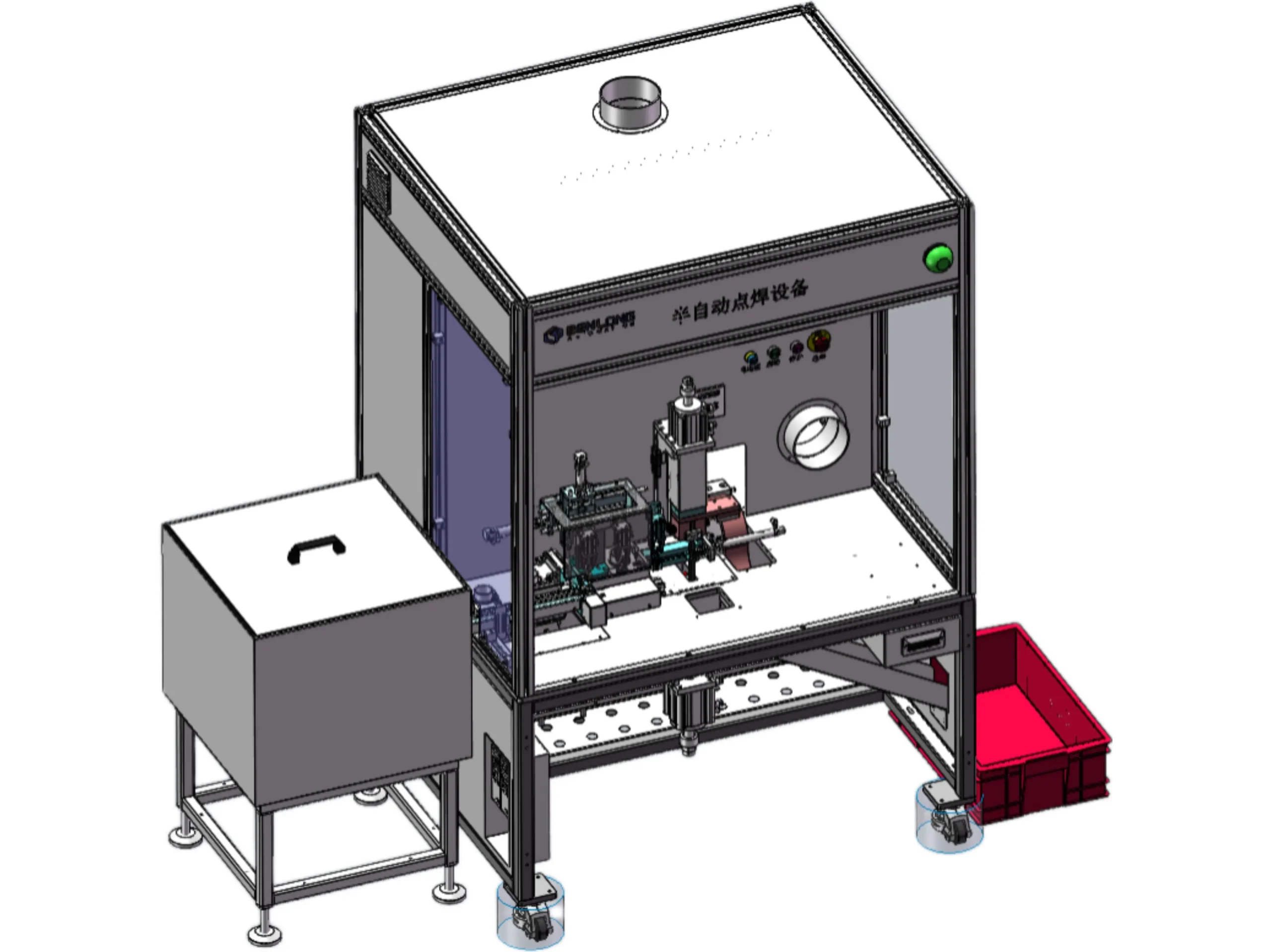
Die automatische Lötmaschine für RCBO-PCBAs ist ein hochpräzises und ausgeklügeltes Inline-Lötsystem für die Verarbeitung von RCBOs. Sie unterstützt RCBOs mit einer Größe von 17,8 mm ± 0,08 mm; andere Größen würden das Gehäuse beschädigen. Der Prozess umfasst mehrere Automatisierungsstufen: Materialtrennung, servogesteuerte Verteilung auf drei parallele Lötlinien, automatisches Erkennen, Anheben und Positionieren, Löten an drei Positionen (Station A) und Zusammenführen vor einem zweiten Lötvorgang (Station B). Abschließend erfolgt der automatische Transport zur Weiterverarbeitung.
Zu den wichtigsten Merkmalen gehören der schnelle Werkzeugwechsel für verschiedene RCBO-Varianten, die Parameteränderung per Knopfdruck über das HMI und Vorrichtungen, die sich stufenlos per Rezeptauswahl oder manuell anpassen lassen. Das System ist für den kontinuierlichen Inline-Einsatz konzipiert, steigert die Produktionsgeschwindigkeit und minimiert menschliche Fehler beim Löten. Die Förderbandkonfigurationen, Löteinstellungen und Vorrichtungsdesigns sind speziell auf Ihre RCBO-PCBA-Geometrie und Ihre Produktionskennzahlen abgestimmt.
Standardlieferzeit: 45–60 Tage | Schnellwechselsystem für Werkzeuge | 3-Linien-Parallelschweißen
Was ist eine automatische Lötmaschine für RCBO-PCBA-Kabel?
Ein automatisiertes Lötsystem mit RCBO (Fehlerstromschutzschalter mit Überlastschutz) ist eine Maschine, die mit spezieller Inline-Löttechnologie arbeitet. Dieses System wurde speziell für das Löten von Leiterplattenbaugruppen (PCA) entwickelt, die zur Herstellung von RCBOs verwendet werden – es ist also nicht mit einer herkömmlichen Selektivlötmaschine vergleichbar. Die RCBO-PCA hat eine durchschnittliche Modulgröße von 17,8 mm ± 0,08 mm. Die installierte Maschine ist daher speziell auf die Abmessungen der RCBO-Komponenten sowie deren elektrische Abstände und thermische Empfindlichkeiten ausgelegt. Im Normalbetrieb können mehrere Lötköpfe gleichzeitig eingesetzt werden, z. B. drei Köpfe an verschiedenen Positionen. Die präzise Positionierung erfolgt über Servoantriebe. Zuführen, Ausrichten und Auswerfen der Leiterplatten erfolgen automatisiert. Zusammen ermöglichen diese Systeme eine hocheffiziente und gleichbleibende Lötstellenqualität in Ihren fertigen RCBOs und führen zu einer geringen Fehlerrate sowie vollständiger Rückverfolgbarkeit zu Ihren Leiterplatten. Da es sich um kundenspezifische Sonderanfertigungen handelt, passen wir die Maschine an Ihr Leiterplattenlayout, die Lötstellenpositionen und Ihre gewünschten Produktionskapazitäten an.
Präzisionsvorrichtung für RCBO-Module; Überschreitung der Toleranz kann zu Gehäuseschäden führen.
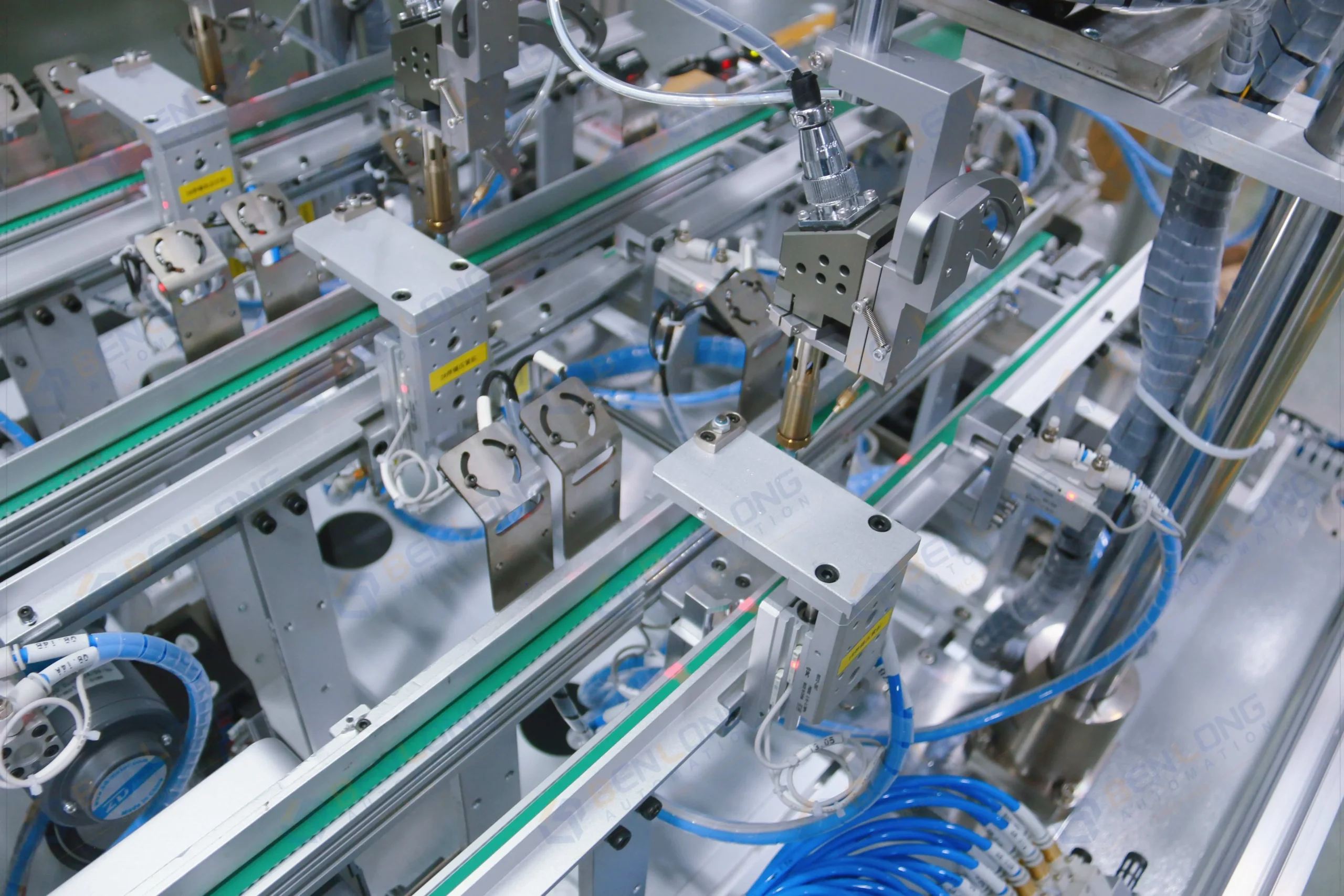
Gleichzeitiges Löten an drei Positionen (Station A) für einen hohen Durchsatz.
Vorrichtungen, die für den schnellen Wechsel zwischen verschiedenen RCBO-Varianten ausgelegt sind.
Zugeschnitten auf Ihre Anforderungen an PCBA-Größe, Lötstellenmuster und Linienintegration.
Lötprozess & Schlüsselstationen

Technische Spezifikationen
| Kompatible RCBO-Modulgröße | 17,8 mm ±0,08 mm (Überschreitung der Toleranz kann das Gehäuse beschädigen) |
|---|---|
| Löttechnologie | Selektives Löten oder Wellenlöten (anpassbar an das PCBA-Layout) |
| Anzahl der parallelen Linien | 3 Förderbänder für die Schweißanlage Station A (gleichzeitiger Betrieb) |
| Schweißpositionen | Station A: 3 Positionen gleichzeitig | Station B: Einzelposition (nach Zusammenlegung) |
| Umstellungsmethode | Schnellwechselsysteme für Werkzeuge; einige Vorrichtungen manuell einstellbar, andere per HMI mit einem Klick. |
| Prozesserkennung | Automatische Produktplatzierungserkennung, Hebe-/Positionierungssensoren, Durchflussüberwachung |
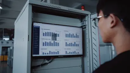
| Steuerungssystem | SPS (Siemens/Mitsubishi) mit HMI, Parametervoreinstellungen pro Produkttyp |
| Materialfluss | Inline-Einlauf aus dem vorherigen Prozess → Trennung → 3-Linien-Verteilung → Schweißen → Zusammenführen → Auslaufförderer |
| Strom- und Luftversorgung | 380 V ±101 Tp3 T 50 Hz | Druckluft für Aktuatoren (Druck auf Anfrage angeben) |
Detaillierter Prozessablauf
Die automatisierte Lötlinie folgt diesem Ablauf (der Bediener stellt die Parameter vor dem Start über die HMI ein):
- Eintrag aus dem vorherigen Prozess – RCBO PCBAs gelangen aus der vorgelagerten Montage in die Maschine.
- Automatische Materialtrennung und -gruppierung – Vereinzelung in einzelne Einheiten.
- Servogesteuerte Verteilung auf 3 Förderbänder – Das Modul befördert die Produkte auf drei parallele Schweißbahnen.
- Automatische Trennung und Gruppierung (schon wieder) – Gewährleistet den korrekten Abstand für die nachfolgenden Schritte.
- Automatische Platzierungserkennung – Sensoren bestätigen die Position der Leiterplatte vor dem Löten.
- Automatisches Heben und Positionieren – Die Produkte werden auf Löthöhe angehoben und fixiert.
- Gleichzeitiges automatisches Schweißen an 3 Positionen (Station A) – Drei Lötköpfe arbeiten parallel.
- Automatischer Transport zum Entladebereich – Nach Station A werden die Produkte weiterbefördert.
- Automatisches Zusammenführen zu einer einzigen Förderlinie – Drei Fahrspuren werden zu einer zusammengeführt.
- Automatische Trennung und Gruppierung (schon wieder) – Bereitet den zweiten Lötvorgang vor.
- Automatisches Schweißen der Station B – Anlöten zusätzlicher Lötpunkte auf der Leiterplatte.
- Automatische Förderung zum Auslauf der Förderanlage – Fertige Leiterplattenbestückungen werden an nachgelagerte Geräte weitergeleitet.
- Zyklus wiederholt sich – Kontinuierlicher Inline-Betrieb.
Technische Kernvorteile (Kundenspezifisches, nicht standardisiertes Design)
Präzisionsvorrichtung für 17,8-mm-Module
Die Vorrichtung ist so gefertigt, dass sie RCBO-Module mit einer Toleranz von ±0,08 mm hält. Eine Überschreitung dieser Toleranz kann die Gehäuse beschädigen – unsere Konstruktion gewährleistet eine gleichmäßige Klemmkraft ohne Überbeanspruchung.
3-adriges Parallellöten
Drei simultane Lötstationen (Station A) steigern den Durchsatz erheblich, ohne dass mehr Stellfläche benötigt wird. Jede Linie arbeitet unabhängig, sodass ein Engpass an einer Linie die anderen nicht beeinträchtigt.
Schnellwechsel und rezeptbasierte Umstellung
Einige Vorrichtungen verwenden mechanische Schnellwechselschnittstellen; andere unterstützen die Parameterumschaltung per Mausklick am HMI. Die typische Umrüstzeit beträgt für neue RCBO-Varianten weniger als 20 Minuten.
Inline-Erkennung und automatische Korrektur
Sensoren zur Platzierungserkennung und Hebe-/Positionierungsmodule gewährleisten, dass jede Leiterplatte vor dem Löten korrekt ausgerichtet ist, wodurch falsch verlötete Verbindungen aufgrund von Positionierungsfehlern vermieden werden.


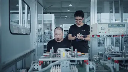
Kundenerfolgsgeschichte – Kundenspezifische RCBO-Lötlinie
Der europäische Hersteller von RCBOs benötigte eine automatisierte Lösung zum Live-Löten von Leiterplatten für verschiedene Produktfamilien (unterschiedliche Leiterplattenlayouts) auf einer einzigen Produktionslinie. Benlong entwickelte daraufhin eine Inline-Lötmaschine mit Schnellwechselvorrichtungen und rezeptbasierter HMI-Steuerung.
Der Durchsatz wurde durch 60% verbessert und manuelle Nacharbeiten aufgrund von Lötfehlern wurden vermieden.
Anwendungen und Integration
Kundenspezifische Entwicklung & Lieferung
Fordern Sie ein individuelles Angebot für das Löten von RCBO-PCBAs an.
Senden Sie uns Ihre PCBA-RCBO-Muster sowie Ihre Lötpunktpositionen und Produktionsziele. Unsere Ingenieure entwickeln daraufhin eine Inline-Lötmaschine mit der passenden Förderband- und Lötkopfanordnung, die optimal auf Ihr Produkt abgestimmt ist.
WhatsApp: +86 150 5837 0007 | E-Mail: xsb@benlongkj.cn | Support in Englisch und Chinesisch
Warum Benlong für RCBO-Lötautomatisierung wählen?
- Mehr als 15 Jahre Erfahrung im Designbereich kundenspezifische PCBA-Lötleitungen für Niederspannungs-Elektroprodukte
- Bewährte Vorrichtungskonstruktion für 17,8 mm ±0,08 mm Module (toleranzempfindlich)
- 3-Leiter-Parallellötarchitektur für hohen Durchsatz
- Schneller Wechsel und rezeptbasierte Umstellung für mehrere RCBO-Varianten
- Weltweiter Service und Ersatzteilsupport
Ein typisches kundenspezifisches System umfasst
Automatische Lötanlage bestehend aus: · Inline-Förderband mit Ein- und Auslaufmodulen; 3 parallele Lötlinien an Station A; 1 Lötlinie an Station B; Automatische Materialtrenn- und Gruppierungsstationen; Sensoren zur Positionserkennung; Hebe- und Positioniermodule; Lötköpfe (für jeden Prozess); SPS mit HMI (Siemens); Schnellwechsel-Vorrichtungssatz; Schutzvorrichtungen; Installation und Inbetriebnahme; Einjährige Garantie
Häufig gestellte Fragen
Die Vorrichtungen sind so konstruiert, dass die Toleranzen der Module eingehalten werden. Wird diese Toleranz überschritten, besteht die Gefahr, dass das Produkt durch zu starke Kompression oder fehlerhafte Positionierung beschädigt wird, was zu minderwertigen Lötstellen führen kann. Wir empfehlen Ihnen daher, Ihre Bauteile vor dem Löten zu prüfen und alle, die diesem Standard nicht entsprechen, auszusortieren.
Ja, die Position jedes Lötkopfes und der Abstand zwischen den Förderbändern lassen sich ändern oder anpassen. Bei größeren Layoutänderungen stehen Schnellwechselvorrichtungen und HMI-Parameter auf Basis von Rezepten zur Verfügung. Der Wechsel von einer Produktversion zur anderen dauert in der Regel 15 bis 20 Minuten.
Mithilfe von Durchlicht- und induktiven Platzierungssensoren wird überprüft, ob die Leiterplatte korrekt positioniert und eingesetzt ist, bevor das Hub-/Positionierungsmodul aktiviert wird. Falls ein Teil fehlt oder ein Teil nicht an der vorgesehenen Position ausgerichtet ist, stoppt die Maschine, bis sie sich im richtigen Teil befindet, oder sie gibt das Bauteil ab.
Die Vorgehensweise hängt von Ihrem PCBA-Design ab. Bei gemischten SMT- und THT-Leiterplatten verwenden wir üblicherweise selektives Löten mit Programmierdüsen. Bei relativ einfachen Layouts kann jedoch auch Wellenlöten zum Einsatz kommen. Wir empfehlen Ihnen, uns PCBA-Muster zur Prozessbewertung zuzusenden.
Die Maschine kann Gut/Schlecht-Signale von SPI- oder Bestückungsautomaten über Standard-I/O- und Ethernet-Kommunikation (Modbus TCP und Profinet) empfangen. Zusätzlich kann sie mit einem Barcode-Lesegerät integriert werden, um Lötparameter mit der Seriennummer jeder Leiterplattenbaugruppe zu verknüpfen.
Verwandte Produkte
Halbautomatische Schweißmaschine
Details anzeigen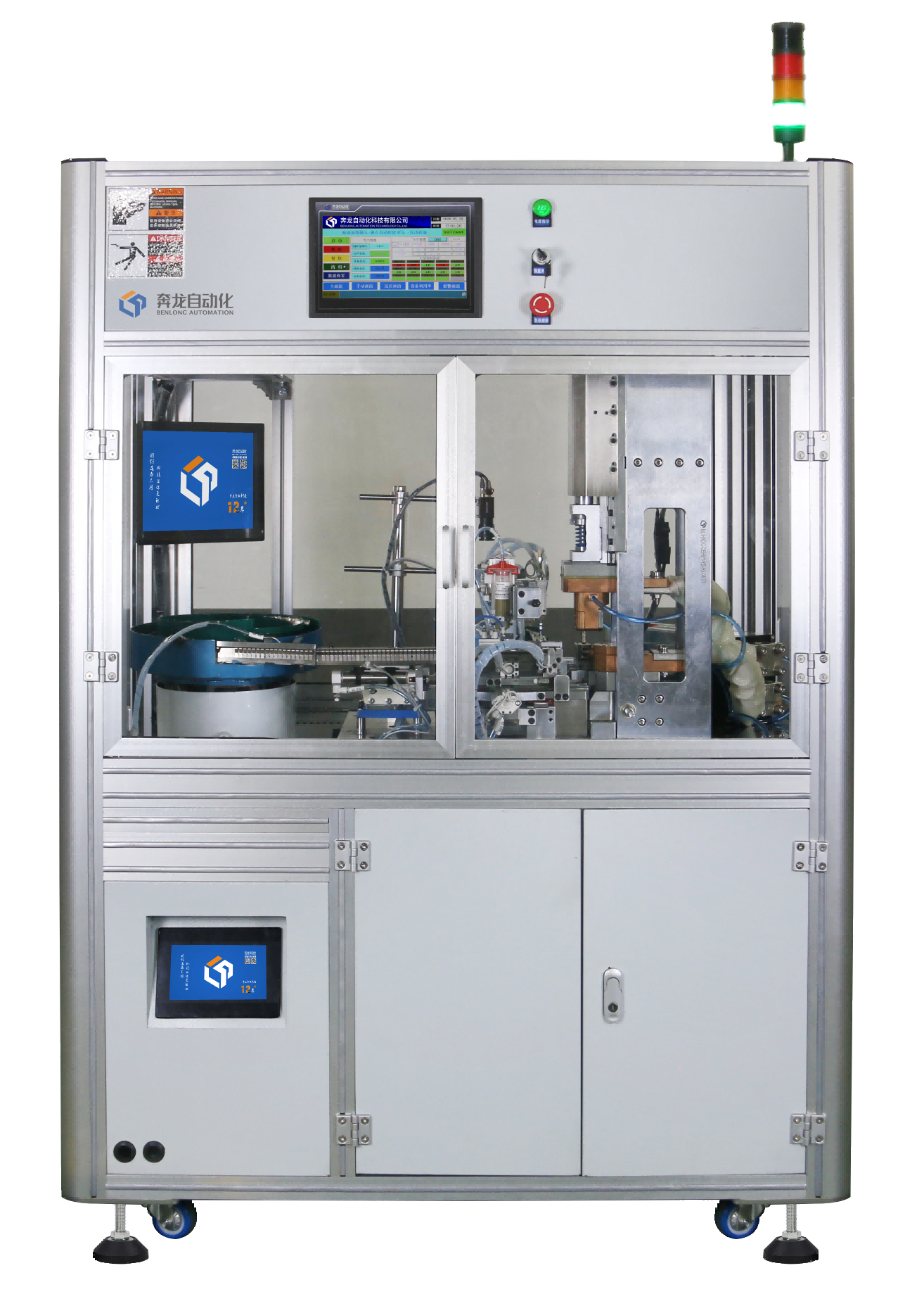
Silberpunkt + Kontakt automatische Schweißmaschine
Details anzeigen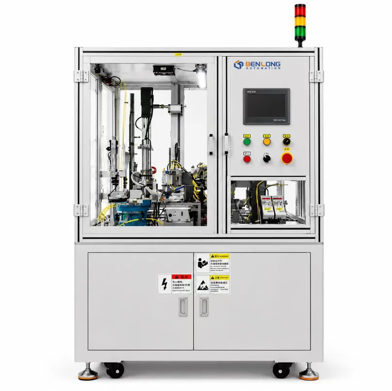
Verzögerungsrohr + Polschuh automatische Schweißmaschine
Details anzeigen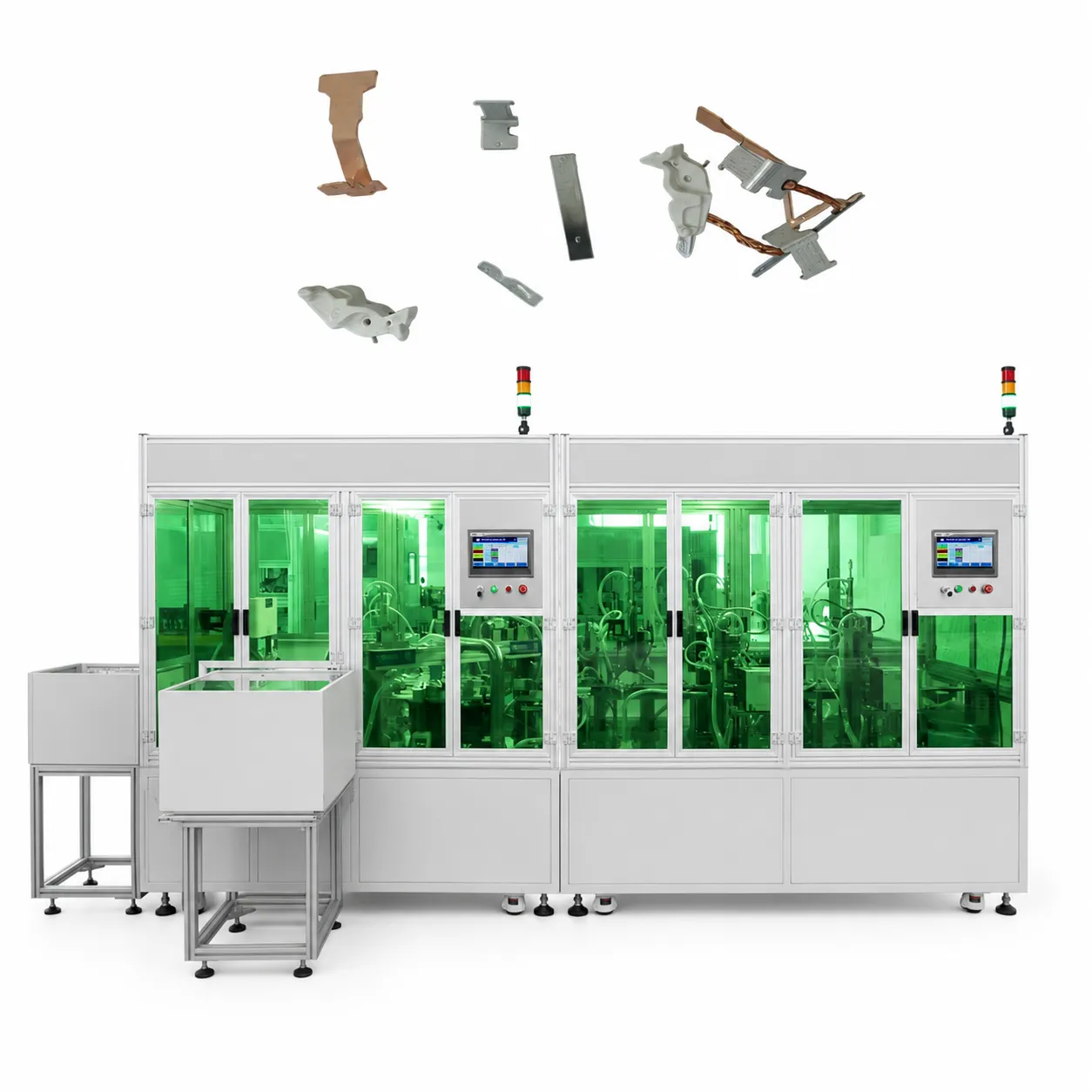
MCB-Thermoauslöser, automatische Schweißleitung
Details anzeigen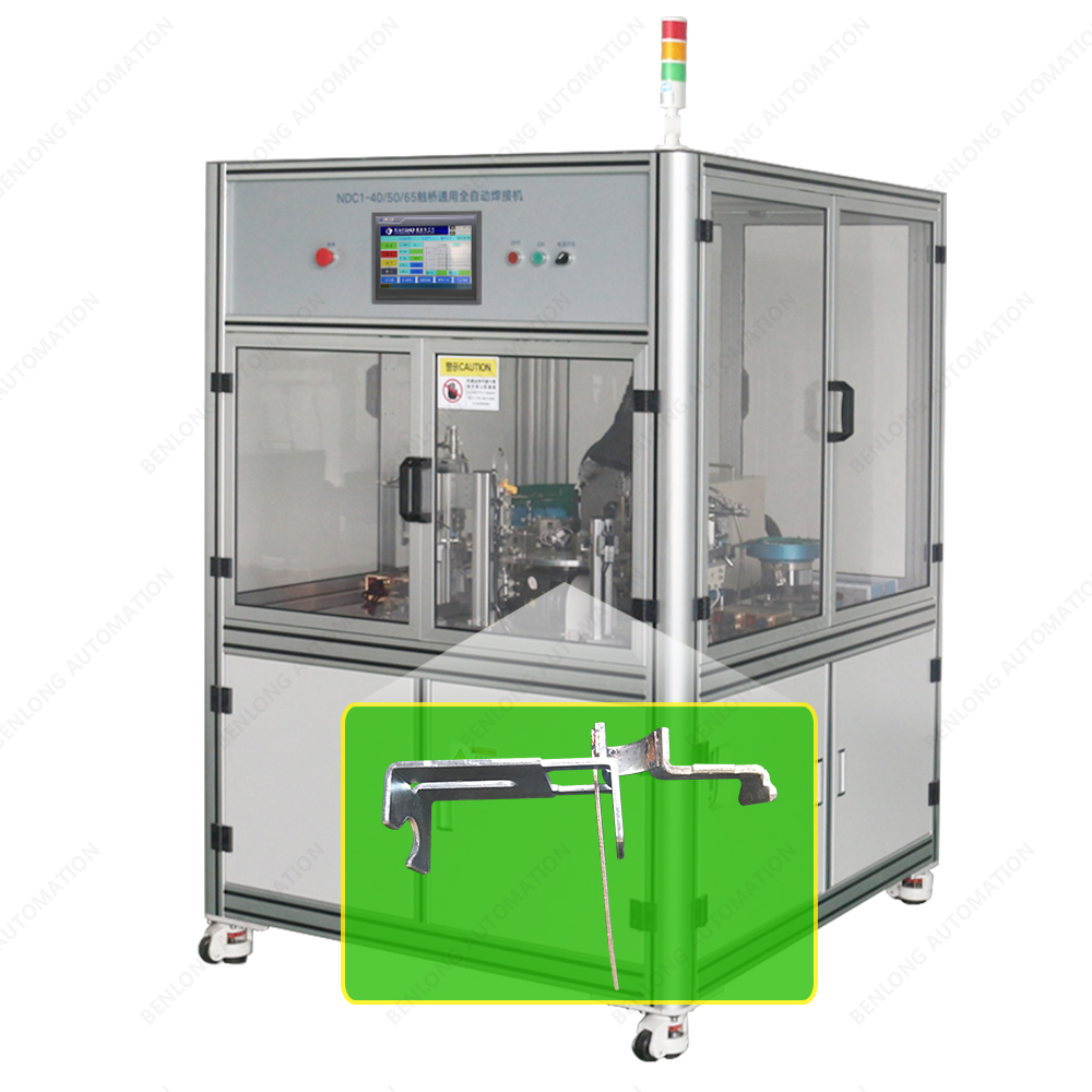
MCB Bimetall-Trägerrahmen-Schweißmaschine
Details anzeigen