benlong


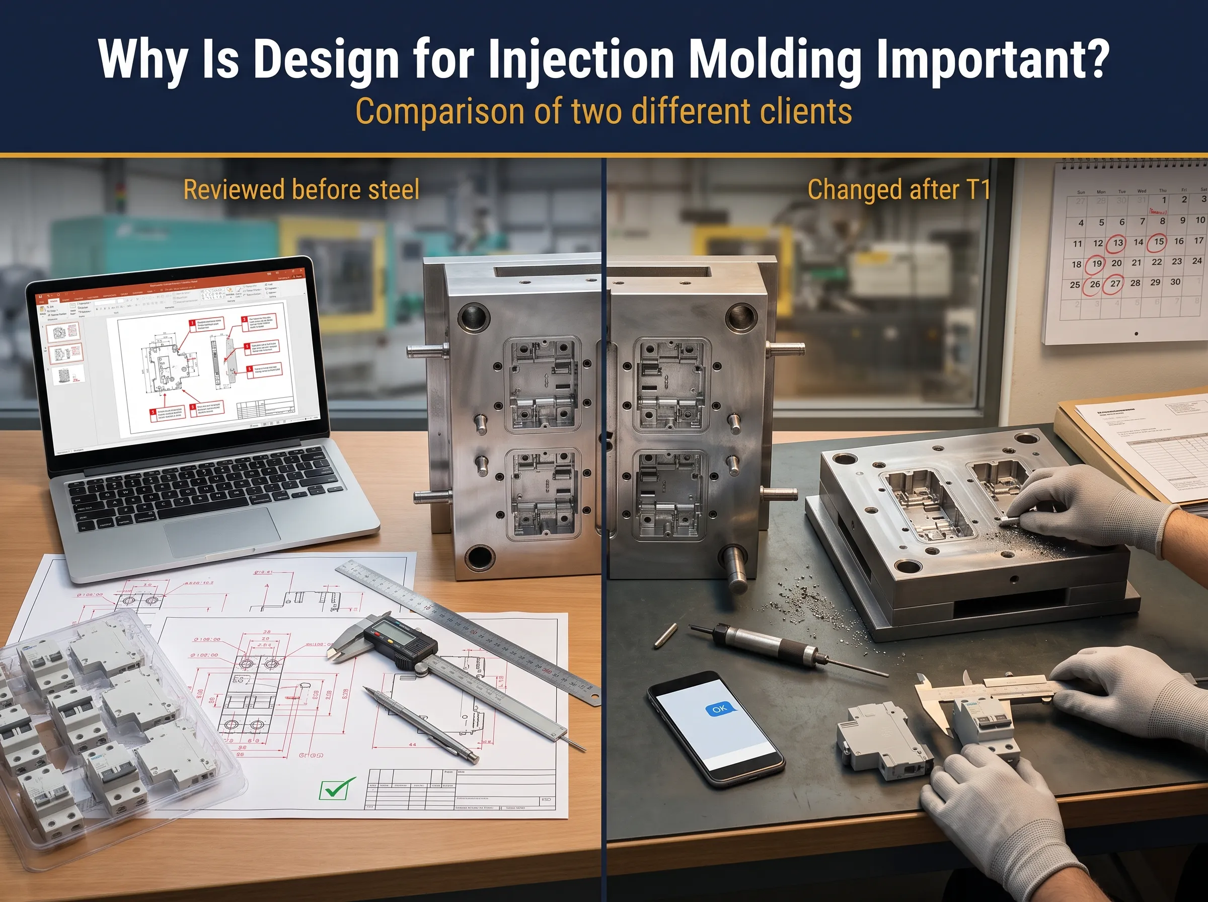
Why Is Design for Injection Molding Important? Comparison of two different clients
The successful injection mold design is crucial in determining whether a product from the mold works right the first time or after three costly steel changes. In the case of a miniature circuit breaker, the permissible margin is limited. It is understood that the MCB housing cannot vary even by a few tenths of a millimeter, as this will lead to the shift of a bimetal strip and the change of the contact gap, which automatic switching device cannot allow.
Benlong Automation builds MCB and MCCB assembly and testing equipment in Wenzhou, China, and we also supply the injection molds that feed those lines. That puts us on both sides of the problem. We design the tool, and then we watch its parts run through an MCB automatic assembly line, where every 0.05 mm of variation shows up as a jammed feeder or a rejected breaker.
The main goal is to answer to one of the most frequent questions of the customers. The project was aimed at explaining the importance of the design phase before cutting the steel, how to apply DFM to MCB project, what are the respective responsibilities of mold buyers and mold makers, and the comparison of two cases from opposite sides in terms of the outcome: OMINSU from Vietnam and Walton company from Bangladesh.
Why is design for injection molding important? Because the design locks in quality, cost and lead time before any steel is cut. A change made on the drawing costs an engineer an hour. The same change made after the mold is built means new inserts, another trial and weeks of delay. For certified parts such as MCB housings, it can also put the certificate at risk.
In terms of most plastic components, the main purpose of design for manufacturing (DFM) is minimizing the cost. An MCB also needs to perform its functions safley. There are five reasons to note.
- Cost. The cycle time depends on the wall thickness, the cavity count determines the shots per hour, and the choice of steel decides on the service life. It is easy to change anything in design. But making changes to the tool means that one will have to use welding, remachining or have to make a new insert. Each operation brings in risks of tool failure.
- Function. An 18 mm MCB borrows a bimetal slice, coil, arc chute with splitters, latch, springs and two contacts. The walls of plastic hold the elements in place, but they also play the role of a guide. A rib that is 0.1 mm too high will load the latch and change the force of switching on. An oversized pocket will allow the arc chute to move due to short circuit.
- Certification. An MCB is certified according to IEC 60898-1 . To receive a certification it is necessary to have a product consisting of all the parts, including housing material and creepage distance. If the design of the housing is changed, one will have to re-certify. A smart approach would be to have the understanding of invariable features prior to starting the design.
- Lead time. Each test round takes 2-4 weeks. Two test rounds for an export order, paid by letter of credit (L/C), results in exceeding the period of shipment in L/C. As a result, there is an amendment of the order, bank comission and troubles for a buyer.
- Automation. The parts that are suitable for manual assembling may not be appropriate for the automated one. Vibrating feeders and cameras need every housing from every cavity to be identical. If there are dimensional differences in the production, machinery does not work and failures occur.
To sum up, the drawing stage is the cheapest stage. Delaying each decision leads to multiplying expenses to correct the error. It is valid in case of screws, nuts, and protective devices such as an MCB where the time of tripping is counted in seconds.
Injection Molding Tool Design for MCB Parts: A DFM Checklist
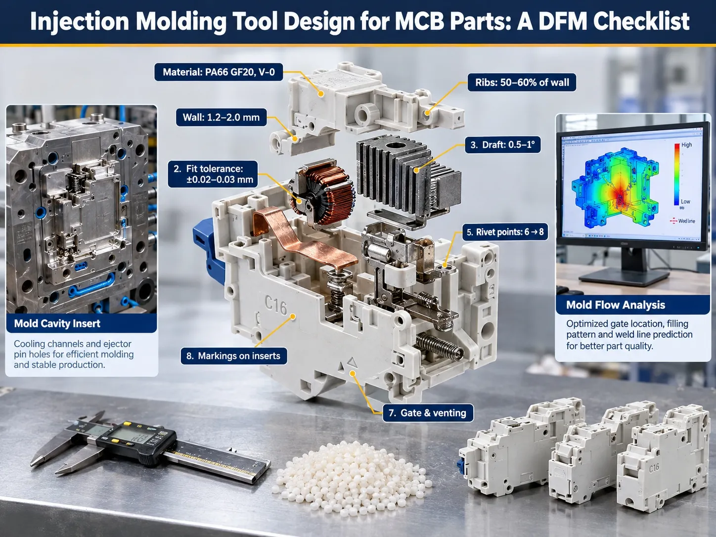
The design process of a quality injection mold tool should begin with the design of the parts and not with the choice of material. Prior to the estimation of manufacturing costs, an engineer must analyze each component of the MCB so that it can be evaluated according to the injection molding design factors. The table shown below outlines the basic injection molding design factors that are particularly important for manufacturers of plastic circuit breakers.
The numbers below should be treated as approximate reference numbers; in other words, they are typical values belonging to glass-filled polyamide-66 housings. These numbers represent just a small part of the complete DFM review process. In general, the final numbers for each project are determined by each client independently using their own product specifications, the manufacturer of the resin data sheet and the results of mold-flow analysis.
| Design item | What we check | Why it matters for an MCB |
|---|---|---|
| Material | Flame-retardant PA66 + 20% glass fibre (GF20); UL 94 V-0 grade; drying before molding | Housings must pass glow-wire tests and stay rigid near the arc chute; glass fibre also makes shrinkage direction-dependent |
| Shrinkage allowance | Shrinkage rates taken from the resin data sheet, applied separately along and across the flow | Using one average shrinkage value on a glass-filled part shifts pivot holes and mating faces |
| Wall thickness | Nominal 1.2–2.0 mm; local variation kept within about 25% of nominal; thick zones cored out | Thick spots near terminals sink and leave voids that weaken screw bosses |
| Draft angle | 0.5–1° on outer walls, more on textured faces; specified per surface on deep internal pockets | Mechanism pockets need minimal draft, but it must be on the drawing or pivot fits drift |
| Ribs and bosses | Rib thickness 50–60% of the wall; boss outer diameter about 2× the hole | Rib ends locate the bimetal and coil; oversized ribs cause sink marks on the visible face |
| Snap-fits and undercuts | Which features need slides or lifters; whether a snap-fit can be redesigned to release in the opening direction | Every slide adds cost and a parting line; a new snap-fit design can change the whole mold structure |
| Rivet points | Number, position and diameter of the rivet holes that join the two half-shells | Going from 6 to 8 rivets changes clamping load, core pins, ejector layout and cooling |
| Internal fit tolerances | Functional dimensions (pivots, latch pockets, contact seats) flagged separately, typically ±0.02–0.03 mm | These set trip force and contact pressure; general dimensions can stay looser |
| Parting line | Location of the split between the two mold halves on each part | A parting line across a sealing or creepage surface leaves a witness line or flash where it does most harm |
| Gate and venting | Gate on a non-functional wall; vent depth around 0.01–0.015 mm for PA66 | PA66 flows thin and flashes easily; flash in a latch pocket can stop the breaker tripping |
| Ejection | Ejector pin positions on non-functional, non-visible faces; enough pins to push thin walls evenly | Pins on a mating face leave marks that change the fit; too few pins bend thin housings on ejection |
| Cooling | Cooling channels balanced across cavity and core, close to thick sections | Uneven cooling warps long side walls and lengthens the cycle |
| Multi-cavity balance | Naturally balanced runner, confirmed by mold-flow, for 2, 4 or 8 cavities | An automatic line sees parts from every cavity; one slow cavity becomes a reject stream |
| Mold steel | Cavity in S136H or H13; mold base in S50C or P20 | Glass fibre is abrasive; hardened cavity steel keeps dimensions stable over a long tool life |
| Markings | Raised vs recessed text; interchangeable inserts for ratings such as C16 or C32 | Recessed text on the part is raised in the steel and easy to machine off; raised text on the part is engraved in steel and needs welding to remove |
The design process of a quality injection mold tool should begin with the design of the parts and not with the choice of material. Prior to the estimation of manufacturing costs, an engineer must analyze each component of the MCB so that it can be evaluated according to the injection molding design factors. The table shown below outlines the basic injection molding design factors that are particularly important for manufacturers of plastic circuit breakers.
For tolerances, we recommend referencing ISO 20457, the international standard for tolerances on plastic moulded parts, whose second edition was published in August 2026, and putting tight values only on the dimensions that truly affect function. If your part already follows the general rules in our injection molding guide, most of this checklist will already be in good shape.
Who Is Responsible for What: Buyer and Mold Maker
The majority of disagreements over mold projects have nothing to do with bad machining or bad steel. The crux of the issue usually revolves around who made which decision and when it was made. The typical injection mold contract divides responsibilities between the mold maker (Party A), who owns the product, and the buyer (Party B), who owns the tool.
| Area | Buyer (Party A) | Mold maker (Party B) |
|---|---|---|
| Product design and function | Owns the product design, its function and its performance | Gives DFM advice; does not change the product without written approval |
| Product data | Supplies product drawings or 3D files, or a physical sample, and states in writing which one governs | If only a sample is supplied, scans or measures it and prepares drawings for the buyer to approve |
| Drawing approval | Reviews and approves the drawings, including all critical dimensions | Submits drawings with critical dimensions and tolerances clearly marked |
| Mold design | May review the mold layout (gates, parting line, ejection) if it wishes | Designs the mold structure, gating, cooling and ejection to the approved drawings |
| Mold manufacture and trials | Attends or reviews trials and inspects samples | Builds the mold, runs T1/T2 trials and supplies samples with a dimensional report |
| Sample conformity | Confirms that samples meet the approved drawings | Corrects, at its own cost, any deviation from the approved drawings |
| Changes after approval | Pays for and allows time for engineering changes it requests after drawing approval | Quotes the cost and schedule impact of each change before carrying it out |
| Certification | Certifies the finished product (for MCBs, to IEC 60898-1 or national schemes) | Supplies material and dimensional records that support certification |
A crucial part of this process is obtaining approval of the drawings from the customers. After a buyer gives approval for the drawing, this drawing will serve as a model for constructing and verifying the production mold. Although a sample may also be used for guidance, it works only if stated in the approval provisions, as well as in the contract with respect to the dimensions to be taken into account.
Walton vs OMINSU: Two Clients, Two Outcomes
Both projects involved MCB housing molds of equal complexity and the clients had no previous experience in mold-making. This is hardly surprising as MCB manufacturers are breaker specialists, not tools manufacturers. The difference between the two results does not involve toolmaking or steel. The distinction lies in the way data on the product was delivered followed by how thoroughly the drawings were scrutinized prior to the opening of the mold.
OMINSU Vietnam: Every Drawing Reviewed
In 2025, OMINSU Vietnam Co., Ltd contracted us to create the MCB mold. Instead of just sending us a sample, OMINSU provided us with its own set of drawings to work with. As a result, all dimensions in our drawings could be traced back to OMINSU`s original product data.
Whenever we send them a mold drawing for approval, the OMINSU team checks the drawing sheet by sheet against the product drawings, returning us a PowerPoint document with comments on every change that needs to be done: the dimension, the value and the reason for the change. Thus, our engineers were able to perform the work based on this document. All corrections were made on paper before any actual work started.
However, no special knowledge of mold engineering was needed. What was needed was simply the basic product information, time, concentration and a seemingly simple way of conveying the changes needed.
Walton Bangladesh: Approval Without Review
Walton’s undertaking entailed adjusting the C45-type MCB already accredited. The revisions contained a snap-fit structure, elimination of the seal-cover, eight rivet spots, and a metal detail added below the washer.
This is how the events unfolded:
1. The RFQ stated that requirements for the final product stipulate to comply with the physical sample.
2. We performed 2D drawings, which got approval via WeChat followed with a message stating that “Ok. Go!” and no comments on the measurements.
3. 3D-printed components were made and the assembly process was demonstrated in video format. The modifications never came.
4. After the receiving the T1 samples, Krogan asked for the dimensions of internal parts to match the original physical sample.
The assumption of Walton is correct as they had to ensure that the product already certified is protected. Maintaining the same internal structure is what good engineering means. However, the key to the issue is timeliness. The same comparison made at the drawing stage would take several days.
Side by side, the two projects looked like this:
| OMINSU (Vietnam) | Walton (Bangladesh) | |
|---|---|---|
| Product data supplied | Customer’s own product drawings | Physical sample; 2D drawings prepared by Benlong |
| Drawing review | Sheet by sheet, with written PowerPoint markup | Approved by chat message, no dimensional comments |
| Reference for dimensions | Customer’s product drawings and approved mold drawings | RFQ named the physical sample; approval was given on the drawings |
| First major change | Drawing stage | After T1 samples |
| Cost of the change | Engineering hours on paper | Insert rework plus an extra trial round |
| Result | Smooth trials | Re-trial and L/C amendment |
What We Changed
We might have considered the Walton project to be good fortune and moved on, but instead we assessed what our internal procedures allowed to take place, and put into place three different improvements.
Written frozen drawings before any steel is cut. Now before there is any cutting of steel, the client must sign a drawing freeze confirmation detailing the revision and important dimensions. And we cannot rely simply on a chat message anymore.
Scanning the sample first. When a client gives us a sample instead of the drawings of the goods, we make sure to scan it and mark its dimensions before the design process begins. There must be a written confirmation about which dimensions pertain the sample and which ones correspond to the drawings.
Markup template for each customer. Now we provide our clients with a simple template for comments, inspired by the Powerpoint method of OMINSU, in such a way that they need no special knowledge of molds to analyze the drawing.
How Buyers Can Review a Mold Drawing Without Being a Mold Expert
One does not require to comprehend cooling designs or ejector plates in order to keep the product safe. The quality of injection design review relies on just a few simple questions which anyone from a braking engineer’s profession can easily answer.
- Which benchmark governs your case? Write down so and list explicitly in the approval where the drawing, 3D file or physical sample is considered a master.
- Have the critical dimensions been marked? Make sure that every latch pocket, hinge, seating position and port is marked with tolerances you agree with.
- Is it still possible to fit the new parts to old ones? Overlay the mechanism and new housing drawing and check clearances.
- Have the certified specifications changed? Compare the dimensions, thickness of walls around live units and material class and check it with your certified design.
- Do the notes adhere to standards? Check for the text of your rating, stamps confirming your compliance with the standards and your logos.
- Have the changes been incorporated completely? If you altered an existing product make sure to outline each change in the drawing.
- Have your comments been recorded? Return your comments not in a message but as a marked-up copy and do not forget to include a revision number in the file name.
- Have you approved the document? Make sure to mark your approval in writing and only after you get the answers to all the questions above.

How to Design for Injection Molding: Our 6-Step Process
If you are working out how to design for injection molding when your product is an MCB, you will need to follow the sequence we describe here. It is a condensed version of our full MCB injection mold development process.
- Requirement analysis. Collect all necessary data on the project including product design drawings or 3D CAD files, physical samples if available, type of plastic resin to be used, production volume as to the future production and certification status or its possibility.
- Design for manufacturing. Go through the above checklist and generate a document describing the ways each element of the MCB design was affected by the design considerations.
- Analysis of mold flow. Simulate filling, packing, cooling and warping to determine the location of gates, balance of mold cavities and make projections on weld lines before the steel is cut.
- Final drawing. Get the customer sign the final drawing. All changes from now on shall be considered a change request and shall impact the costs.
- T1 and T2 trials. First shots of the mold are compared against drawing and the physical samples if available. Our standard MCB injection mold package includes 1000 approved parts and a dimensional report.
- Functional tests. The sample parts are assembled into complete breakers and run through trip calibration, dielectric and mechanical tests, the same checks an MCB testing laboratory performs, before the mold is released for mass production.
Generally we need about 45 days for the making of the MCB injection molds after the last drawing is signed. The time necessary for the drawing approvals is not included into this period because it cannot be estimated in advance. The faster the drawings are checked and approved the sooner they are ready for acceptance testing of new designs.
The same six steps apply to any plastic injection mold design. MCB parts simply leave less room for error.
Injection Mold Gate Design for Small Electrical Parts
The importance of the design of the gate of the injection mold is that it determines the location of weld lines, anisotropic strains and fiber orientations in the case of a small produced electrical element. Four rules are applied to the production of molding casings of MCBs.
To avoid any problems, the gate must not be situated near latches or contacts. Even the existence of a gate vestige, local stress or weld line in the latch pocket can influence the capacity of the mechanism to trip or fail because of high temperatures.
Submarine gates must be used. A sub-gate is cut automatically after the injection mold is opened, and this makes the operation easier for molds.
In order to plan fiber orientation, it must be remembered that glass fibers orient along the flow so that glass-filled PA66 shrinks less in that direction. Therefore, the placement of the gate is critical in determining the direction of the movement of the wall.
The runner should have to be balanced. In the case of 4 or 8 cavities, all of them should be filled at the same time and under equal pressure.
Built to the Same Standards as Global Breaker Brands
MCBs have maturity that makes them a highly standardized product. After all, the most competitive products benchmarked against, such as Schneider Electric Acti9 iC60, ABB S200, Siemens 5SL, Legrand DX³, and CHINT NXB, are made according to the basic IEC 60898-1 standard along with an 18 mm module that fits into a 35 mm DIN rail. This uniformity across brands is why a new MCB can be compared with others in tenders and is the basis of the designs of our molds.
This means, in practice, that we design for compliance with the IEC 60898-1 and IEC 60947-2 testing standards, using the 18 mm module width and DIN-rail clip design, flame-resistant PA66 plastic, as well as C45 and DZ47 internal designs that exist in many regional brands.
Mold Projects We Have Delivered
Every project below went through the same injection molding mold design process described above.
| Client | Country | Project |
|---|---|---|
| KEAZ | Russia | MCB injection molds |
| ROMEL Electrical Equipment | Ethiopia | MCB injection molds |
| PT. Lelco Trindo Nusantara | Indonesia | MCB injection molds |
| OMINSU Vietnam Co., Ltd | Vietnam | MCB injection molds (2025) |
| Walton | Bangladesh | Molds for a modified C45-type MCB |
Planning your first MCB tool? Our guide to MCB injection mold manufacture covers steel, cavitation and cost drivers in more depth.
Schneider Electric, Acti9, ABB, Siemens, Legrand, CHINT and other brand and product names are trademarks of their respective owners. They are mentioned only as industry reference points; no partnership or endorsement is implied.
Frequently Asked Questions
How to design a mold for injection molding?
According to the strategy discussed above, we must begin with working on the part instead of making a mold. First, we must verify the resin, wall thickness, functional dimensions and draft and run the DFM process using broken theory flow software. In short, how to design a mold for plastic injection comes down to settling every decision on paper first and validating it with T1 samples.
What is the best software for injection mold design?
A definitive best package does not exist. Mold modelling is done utilizing Siemens NX with Mold Wizard, PTC Creo, and SolidWorks while Cimatron and ZW3D are the major brands employed in tool shops. Autodesk Moldflow and Moldex3D are by far the most popular programs for flow simulation. What matters the most is not the brand of product used, but verifying the ability of mold maker and customer swap STEP or native files.
What are the design standards for injection molds?
Three levels of categorizations exist. Generally, mold parts conform with catalog standards such as HASCO, DME or Misumi and SPI (currently PLASTICS) mold grades identify expected mold lifetime, whereby Class 101 corresponds to more than a million cycles. Additionally, part tolerances can conform with ISO 20457. Product standard occurs above both layers. For instance, the standard for MCB enclosures is IEC 60898-1 or IEC 60947-2.
Is injection molding better than 3D printing?
While 3D printing is not efficient for cutting volume production, it is great for developing 3D printed prototypes since there is no tooling involved and the technology is useful for evaluating the fit and assembly of prototypes, something done for MCB layouts ahead of the actual manufacturing process. Injection molding starts to be more advantageous when the number of parts escalates to thousands as far as part pricing and strength are concerned. It is common to mix both technologies in practice. Our article on rapid prototyping companies covers the printing side, and what is injection molding covers the molding side.
References
- IEC 60898-1:2015+AMD1:2019 CSV, Circuit-breakers for overcurrent protection for household and similar installations (International Electrotechnical Commission)
- ISO 20457:2026, Plastics moulded parts: Tolerances and acceptance conditions (International Organization for Standardization)
Send Us Your Sample: Free DFM Review
Have a breaker you want to tool up, or a certified product you need to copy without surprises? Send us your product drawings, 3D files or sample. Within 48 hours, our engineers will return an annotated DFM report covering wall thickness, draft, gate options and the dimensions we recommend freezing, before you commit to steel.