benlong



High Voltage Test Explained for Electric Products
Every low-voltage product that departs from a factory bears a hidden commitment: the insulation between its electrical circuits and the hand that will one day touch the panel will work. Nothing on the assembly line ensures this commitment except for the few seconds of test voltage application. While torque, vision, temperature and magnetic tests indicate whether a product works, only dielectric testing provides the information on whether a product is safe in case of failure. The guide describes the function performed by dielectric testing, voltages that belong to different families of products, construction of benches, use of benches in production processes, reasons why good products can fail, and erroneous ones can pass, and the requirements to machines that are to maintain their performance during the next ten years.
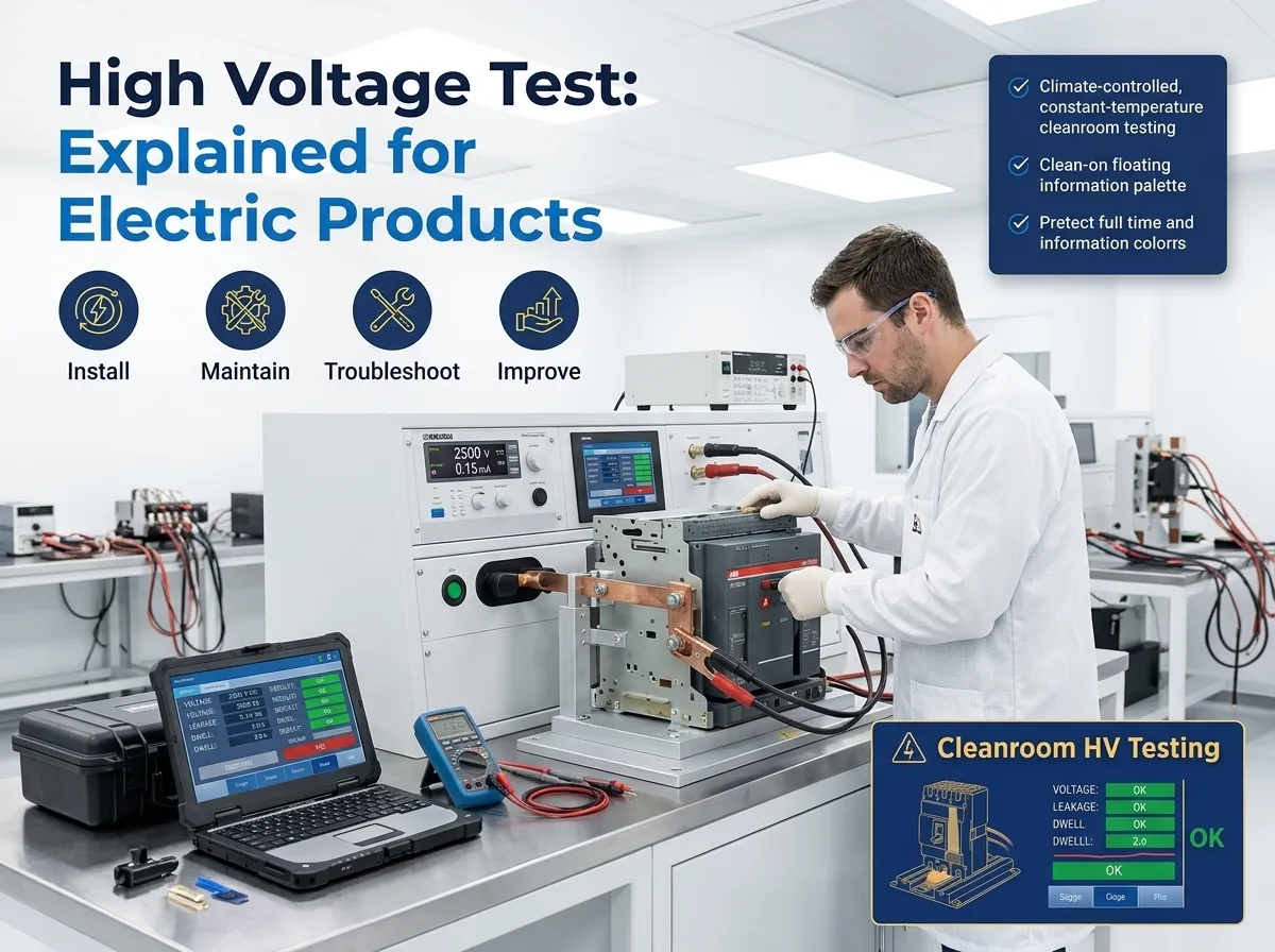
Dielectric testing, also known as a high potential test (hi-pot), is designed to apply elevated AC or DC voltage level between the product’s live part and its accessible surface, between conductive poles, and across open contacts, hold for a predetermined time period, and measure the leakage current. If the leakage is less than the acceptable level and no dielectric breakdown takes place, the insulation system passes the test.
What is proven by a High-Voltage Test?
The high voltage test does not evaluate if a circuit breaker operates properly, how fast it shuts off, or how much current can be stopped. In fact, it only verifies that the insulation system that was part of the product can withstand the voltage that is much higher than that which it will encounter in its lifetime.
The reason for that narrow scope is that three kinds of defects will not be identified along the whole process, but will be recognized at this stage:
– conductive contaminants, such as metal chips from riveting, or silver wastage from contacting welding
– moisture and residues, like humidity absorbed by housing, or flux and cleaning solution
– assembly errors, such as barriers that did not sit properly, or rivets pushing through walls
Neither of these defects can be detected otherwise from the outside. The device that had any of them looks great upon leaving the production line, and works like a charm when powered for the first time and for months afterwards as well.
Type vs Routine Test
Whenever something bought is said to be able to perform type and routine testing, it is not uncommon for customers to find out later that it can’t.
Type testing is performed in a lab, on just a few samples to certify a product. During the testing of the machine the process goes in accordance with the standard: full load voltage is applied, the products have been tested for one minute, the items have been conditioned, the results are measured with calibrated equipment providing high accuracy, and a report is issued for further reference. A routine test – sometimes called a production or hi-pot test – is performed 100% of the time for every item produced, at a speed of a couple of seconds, and with a help of a fixture that is loaded in one movement by the operator.
The laboratory machinery focuses on accuracy of the measurements, while the production machine concentrates on efficiency. Therefore, the device meant for both types of tests ends up not working perfectly for either of them. Before deciding on the price, it is important to specify which type of the process is to be performed.
Test Voltages by Product Family
Electromagnetic voltages for each type of product are not established just like that. For most low-voltage products, it is determined by their characteristics set by the voltage level declared, and then outlined in the specific subcategory of IEC. The following table is designed to offer more information on the level of test voltage to use in manufacturing of a given product.
| Product family | Governing IEC standard | Typical production dielectric test | Notes for line planning |
|---|---|---|---|
| MCB (miniature circuit breaker) | IEC 60898-1 | Roughly 1,500 – 2,000 V AC, around 1 s dwell | Applied live parts to case surface and across open contacts; usually combined with an ON-OFF continuity check. |
| MCCB (moulded case circuit breaker) | IEC 60947-2 | 2,000 V AC and above, around 1 s dwell | Value scales with the declared insulation and impulse ratings; larger frames need higher output and better fixture clearance. |
| RCCB / RCBO | IEC 61008-1 / IEC 61009-1 | Comparable to MCB levels | The residual tripping circuit and electronics need a defined connection state during the test to avoid damaging them. |
| ACB (air circuit breaker) | IEC 60947-2 | Higher levels, typically with insulation resistance measured first | Large creepage distances and heavy conductors make fixture design, not the source, the limiting factor. |
| AC contactor | IEC 60947-4-1 | Programmable up to about 2,500 V AC | Coil circuit to main contacts is the critical path; test is normally bundled with pick-up and drop-out voltage checks. |
| Isolating switches and changeover switches | IEC 60947-3 | Comparable to MCCB levels | Four-pole simultaneous contacting is usually required to keep cycle time acceptable. |
| Surge protective devices | IEC 61643-11 | Insulation resistance and leakage at operating voltage rather than a plain overvoltage stress | A conventional hi-pot sequence can destroy the varistor – test routines must be written for the product, not copied from breakers. |
| Energy meters | IEC 62052-11 | Around 2 kV AC plus impulse requirements | Electronics require defined earthing and short-circuiting of terminals during the test. |
| Solid state relays | IEC 62314 and product specification | Input-to-output isolation check at the declared isolation voltage | The point of the test is galvanic separation between control and load side. |
Treat these figures as planning guidance only and confirm the exact voltage, dwell time and acceptance limit against the current edition of the clause that applies to your product and market. Editions change, and national deviations in India, Brazil, Saudi Arabia and the EU sometimes add requirements.
Components of a High Voltage Test Bench
There are six subcomponents determining whether high voltage testers are consistent in their performance over years or become arguments between the quality assurance and production departments:
- High voltage source and its regulation. The output should be stable during the load changes and during mains voltage sags; unregulated source does not give readings of any sort.
Contact system. Most of the misunderstandings originate from here. The probe pressure, contact material, etc., affect the leakage measurably more than any electrical parameter.
Leakage measurement and arc detection. A current threshold detects breakdowns while the arc detection is capable of catching the very short breakdown.
The chamber and interlocks. The testing room is closed and the electrical circuit cannot be energized while the chamber is open.
Control procedures and recipes. A PLC with an HMI storing parameters for each model helps eliminate operator errors.
Data capture. Voltage, leakage current, duration, etc. are recorded and can be transferred to USB or MES. 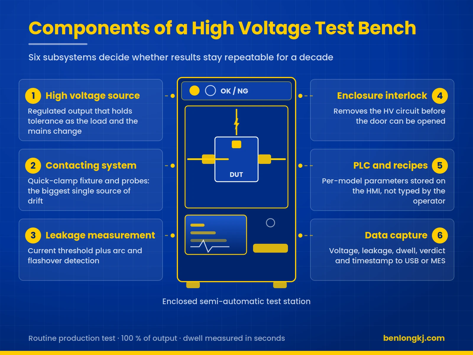
High Voltage Testing Across a Low-Voltage Product Range
Benlong Automation builds high voltage test equipment for every product family made in a low-voltage electrical plant, from standalone benches to stations embedded in a full assembly line. The test bench project range covers the following.
MCB
In the case of miniature circuit breakers, dielectric testing is nearly always combined with other appliances. The MCB automatic magnetic trip test plus ON-OFF and high voltage test machine performs instantaneous trip checking at currents between 5 to 10 times the rated current and verifies mechanics ON-OFF and continuity while performing testing, and a dielectric up to 4,000 volts AC in one PLC-controlled series of devices and cycles of 2.5 seconds or less per pole. Merging the three functions cuts test floor area by around 40 percent against separate benches. Upstream, the semi-automatic thermal trip calibration bench and the long time thermal calibration bench set the bimetal characteristic before any MCB high voltage test machine sees the unit – a breaker rejected for insulation after thermal calibration has already consumed the expensive part of the process.
MCCB
MCCBs are available in typical catalogs with seven or more frame dimensions that used historically seven fixtures and often seven benches. The MCCB semi-automatic high voltage test bench covers 125 A through 1,250 A on one platform. For laboratory work the MCCB laboratory integrated testing bench combines magnetic trip, thermal calibration and long-duration thermal testing, while the manual magnetic trip test bench and the long time thermal calibration bench handle the current-based characteristics.
RCCB and RCBO
Residual current devices offer the function of an additional trip circuit that has to be treated with caution. The RCBO semi-automatic comprehensive test bench sequences residual tripping current and time measurement together with the insulation checks, so that the electronics are in a defined state when the voltage is applied.
ACB
Air circuit breakers are tested in low quantity but bring serious consequences. Therefore the ACB comprehensive test bench can merge loop resistance, insulation, and current characteristics and power consumption into one station.
Contactors require the dielectric check to be read together with coil behaviour, because both share the same failure causes. The AC contactor comprehensive test machine measures contact gap and over-travel, contact synchronisation, dielectric withstand, and pick-up and drop-out voltage in a single automated station.
Accessories, isolating switches and complete lines
The same principles apply to auxiliary and signal contact blocks, changeover and isolating switches, and accessory sub-assemblies. When volume justifies it, these stations stop being benches and become part of an automatic high voltage test line in which calibration, trip testing, dielectric testing, marking and sorting run as one continuous flow – the architecture described in our guide to the MCCB automatic assembly and testing line. For components such as solid state relays the emphasis shifts from breakdown strength to galvanic isolation between input and output, as explained in our note on how to test a solid state relay.
Machine in Focus: Semi-Automatic MCCB High Voltage Test Bench
This bench is the clearest illustration of what multi-frame design is worth. Instead of a dedicated tester per frame size, one platform with quick-change adapters covers the whole MCCB catalogue, which is why a MCCB high voltage test bench of this type typically replaces six or seven single-purpose testers.
| Parameter | Specification |
|---|---|
| Test type | High voltage withstand (dielectric strength) test, phase to phase and phase to ground, with leakage current measurement |
| Compatible frame sizes | 125 A, 250 A, 400 A, 630 A, 800 A, 1,000 A, 1,250 A |
| Cycle time | Typically 5 – 10 seconds per test, depending on model and frame |
| Result output | OK / NG indication, green and red lamp, plus live HMI readout |
| Automation | Semi-automatic: quick-clamp fixture with touchscreen operation |
| Changeover | Under 5 minutes between frame sizes, against 15 – 30 minutes for manual refixturing |
| Control | Omron PLC, MCGS touchscreen HMI, Entai high voltage tester |
| Dimensions and supply | 1,800 x 1,500 x 1,900 mm, 380 V 50 Hz |
| Safety | Enclosed test area with door interlock and emergency stop |
| Delivery | 30 – 45 days manufacturing, pre-FAT at factory, on-site installation and SAT |
Full specifications, video and the customer case in which one manufacturer replaced six testers with a single platform are on the product page for the MCCB semi-automatic high voltage test bench.
Machine in Focus: AC Contactor Comprehensive Test Machine
An AC contactor high voltage test in isolation answers only half the quality question. The isolation test does not account for the fact that most insulation problems with contactors have the same underlying causes as coil and contact problems. Issues such as contamination during coil winding, poor alignment of the armature movement and deposition of silver from the contacts during operation cause similar insulation failures. Performing the dielectric test of the equipment separately from the coil test adds unnecessary variations in handling.
| Parameter | Specification |
|---|---|
| Test functions | Contact gap and over-travel, contact synchronisation, hi-pot dielectric strength, pick-up voltage, drop-out voltage, overvoltage and undervoltage adaptability |
| Dielectric test output | Programmable up to 2,500 V AC with adjustable dwell time |
| Contact gap accuracy | Plus or minus 0.01 mm, measured by linear encoder |
| Synchronisation timing accuracy | Plus or minus 0.1 ms |
| Pick-up and release voltage accuracy | Plus or minus 1 percent of reading |
| Cycle time | 15 – 30 seconds per contactor depending on the number of tests selected |
| Product range | AC contactors 9 A – 95 A as standard, up to 400 A optional |
| Changeover | Under 5 minutes using quick-change tooling and stored recipes |
| Control and data | Siemens PLC with HMI, 50 or more model recipes, export by USB or to MES over OPC UA or Modbus TCP |
| Supply | 380 V plus or minus 10 percent, 50 Hz, hi-pot circuit 220 V |
Specifications, test sequence detail and the European case study in which four stations and three operators were reduced to one machine and one operator are on the product page for the AC contactor comprehensive test machine.
Where the Test Belongs in the Line
The three methods of positioning a test facility are commonly used in the industry, and the selected method impacts the economic aspects of production more than the characteristics of the testing equipment itself.
Inline testing is the most widely used method because it allows for quality control in the production of MCCB and MCBs. All products undergo thorough tests, which are linked to the serial number of the product. All rejects are sent to a special place for unfinished products. The problem of this method is that a defect detected at this stage has already cost all the assembly operations that were conducted previously. Inline testing is performed after an important part of assembly has been finished. This means that the advantages of the method must be considered when it is chosen. The offline method is more appropriate for production of a low number of units of various models. Offline, in a quality laboratory, suits low volumes, mixed-model production, incoming inspection of purchased components and R and D validation; the practice is described further in our article on what an MCB testing laboratory does.
The econometric principle of this method is simple: inline testing pays for itself not through labor costs, but through preventing scrap production. Thus, a factory manufacturing thousands of units of the same product will find it very profitable to apply inline testing within a year, while a company producing 200 items per day of various models may find it more efficient to use semi-automated testing equipment instead.
Why Good Units Fail and Bad Units Pass
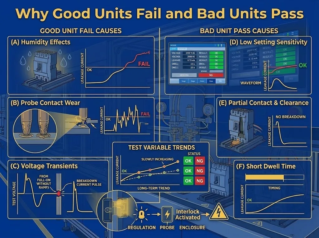
Any factory that employs dielectric withstand testing at volume usually, at one point or another, ends up arguing about whether the machine is performing correctly. The four main sources of arguments include the following:
Humidity is the first one. Nylon and thermoset cases absorb moisture and lead to the increase in surface leakage; hence, a batch that passed the test in February may fail during monsoon rains in July without any changes in the product itself. The second argument is fixture wear: probe tips oxidate, springs relax, and it leads to the fact that contact resistance drift shows as leakage drift. The third argument is with the testing sequence: if voltage is applied instantly instead of gradually, it can lead to transient response, which would not happen in correctly insulated product. The fourth argument comes from the acceptance limit itself, which is set only once during commissioning by somebody who has already left the company and has never readjusted the limit afterwards.
The countermeasure is not representing a stricter limit. It is taking the leakage value and making it recorded. A bench that records the number allows quality engineering to see the distribution changing weeks before crossing the limit; while the bench that simply registers pass or fail does not allow to distinguish between the problem with a process and the problem with measurement.
Safety Is the Degree That Should Not Be Compromised
The danger of thousands of volts in the hands of a worker doing a monotonous job several hundred times a shift is enhanced by their raising familiarity with the problem and the process. A safety breach may take a form of a fully enclosed work area, an interlocking system that disables the high voltage circuit before opening the enclosure rather than after, discharging the test circuit prior to gaining access, an emergency cut-off button within operator’s reach, and clear visual signs that indicate the presence of current in the circuit.
Cases of fatalities occurring in this sector due to ignoring interlocking system have shown that the time lost because of safety regulations does not justify speeding up the cycle for some short-time increased production volumes. Workers should be trained to work with the machine, tested regularly according to schedule, and their performance recorded as an essential part of the safety maintenance process.
Data, Traceability and Audits
Manufacturers that supply utilities, government tenders, and other OEM clients have to keep in mind that there is a commercial aspect of a test report but the technical side is important, too. Audit organizations and clients start asking three important questions: did you manage to get the findings regarding the specific serial number checked, did you prove that the machine was calibrated when the results were obtained, and did you show that the parameters remained unchanged throughout the manufacturing process.
The answers to these questions assume having records on every unit produced and its time of doing it, using recipe driven control systems, providing password-protected access to the parameters, proving the calibration of the measuring device (authentication), and connecting MES to the manufacturing process. The measurement side of this – calibration intervals, uncertainty and choosing a laboratory – is covered in our guide on MCCB calibration machine performance.
How to Specify a Bench: an RFQ Checklist
The variation in the quotations for performing a high voltage test for circuit breakers can be as much as three times more – in many cases it is due to misunderstanding of specifications rather than profit mark-up. Specifics for making an inquiry should include:
①.roduct group, specific models to be tested, and pole configurations.
Applicable standards and markets, if any deviations are present.
②.Requirements for the test voltage, duration of the test and maximum allowed maintenance current or a test sample plus datasheet.
③.Required cycle time and output per shift which imply semi-automatic or fully automatic operation.
④.Changeover rate, e.g a plant changing model two times an hour should get fast workflow more than speed.
⑤.Should any other tests be done at the same workstation? Which ones?
⑥.Requirements for the information whether it is log file, USB transfer or real-time systems integration.
⑦.Logistics: supply voltage, frequency, pressure air system, usable floor space and ceiling height.
⑧.Acceptance protocol includes FAT and SAT scope, training days and warranty conditions.
⑨.Make sure samples are available at the inquiry stage. Nothing accelerates the process faster than the supply of three units of the model in question – fixture design is usually the bottleneck in the project.
Cost, Return and Total Ownership
The capital cost of this category of equipment is influenced by the number of frame sizes needed, the level of automation, data systems available and the brand of testers used. Three main factors have a defining influence on the profitability calculation.
Consolodation is the leading factor – one multi-frame platform replaces six or seven dedicated testers and significantly changes both the equipment budget and the plant size, and unless the space is used in the well- established plant, it does not cost anything. Changeover time is the second parameter – if a product change goes from thirty minutes to five every time it is done three times in one working shift, over one hour of capacity will be returned each day. The third and the hardest to quantify factor is avoided field failure that is at the same time the most critical failure because a dielectric breakdown identified by a customer leads to warranty issues and appears to considered serious in some industries.
On the other hand, there are obvious expenses connected with ownership that offers only in the less detailed quotations: calibration, spare part replacement, spare tester modules and retraining of personnel.
Frequently Asked Questions
What is the distinction between a hi-pot test and an insulation resistance test?
A hi-pot test is when we apply high voltage for a limited period of time and then determine whether or not the insulating material breaks down, resulting in either a pass or a fail result. Meanwhile, an insulation resistance test is conducted using lower DC voltage and we obtain a resistance value from the procedure, which allows us to track it over time. Many testing benches are able to perform both tests: the resistance measurement indicates the slow degradation of the material, while the withstand test confirms its immediate safety.
Should we use AC or DC for the test?
Low voltage product standards usually recommend performing the test with AC for the equipment that is designed to be operated utilizing AC, because this method mimics the conditions in which the insulation will be working. In case the capacitance current would interfere with the measurements conducted with AC, then DC should be used. However, one should follow the guidelines given by the applicable standards rather than pursuing the most convenient option.
Can one bench test several product families?
Testing different types of products on the same bench is only possible if they belong to the same family of products – therefore, multi-frame MCCB concept is widely used. Testing products from different families is considered a bad practice – the differences in the geometry of the fixture, methods of contacting and the test sequence make it very inefficient to use a universal machine.
How often should the tester be calibrated?
Annual calibration is considered a baseline for the calibrations that are done using a traceable standard. Frequent calibration should be made in case of the continuous working process, harsh environment or if it is specified by the customer. Many companies apply daily or weekly functional check of the machine with using a reference sample for preventive measures to detect any potential malfunctioning.
Does high voltage testing damage the tested product?
When the correct routine test with appropriate voltage level is applied, it typically does not lead to deterioration of the non-defective product. However, if one keeps doing the routine type test several times on the same object or applies the voltage level slowly, such actions can contribute to insulation damage.
Specifying Your Next Test Bench
Benlong Automation has built assembly, calibration, welding and testing equipment for low-voltage electrical manufacturers since 2008, with installations across India, Brazil, Turkey, Saudi Arabia, Iran and Southeast Asia. Send your product samples, target cycle time and applicable standard, and our engineering team will return a configuration proposal with fixture concept, cycle time estimate and a return on investment calculation. Browse the full test bench range, review the equipment FAQ, or contact our team directly at xsb@benlongkj.cn.
References
- IEC 60947-2:2024 – Low-voltage switchgear and controlgear, Part 2: Circuit-breakers
- IEC 60898-1:2015 – Circuit-breakers for overcurrent protection for household and similar installations
- IEC 60947-4-1:2023 – Contactors and motor-starters, electromechanical contactors and motor-starters
- IEC 60664-1:2020 – Insulation coordination for equipment within low-voltage supply systems
- Benlong Automation – ACB Comprehensive Test Bench: loop resistance, insulation and withstand voltage, current characteristic and temperature rise testing