benlong


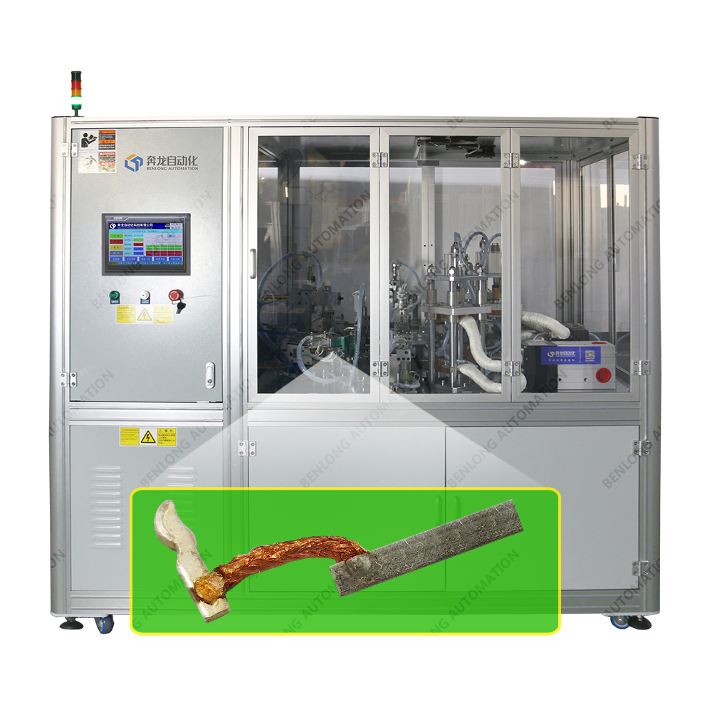
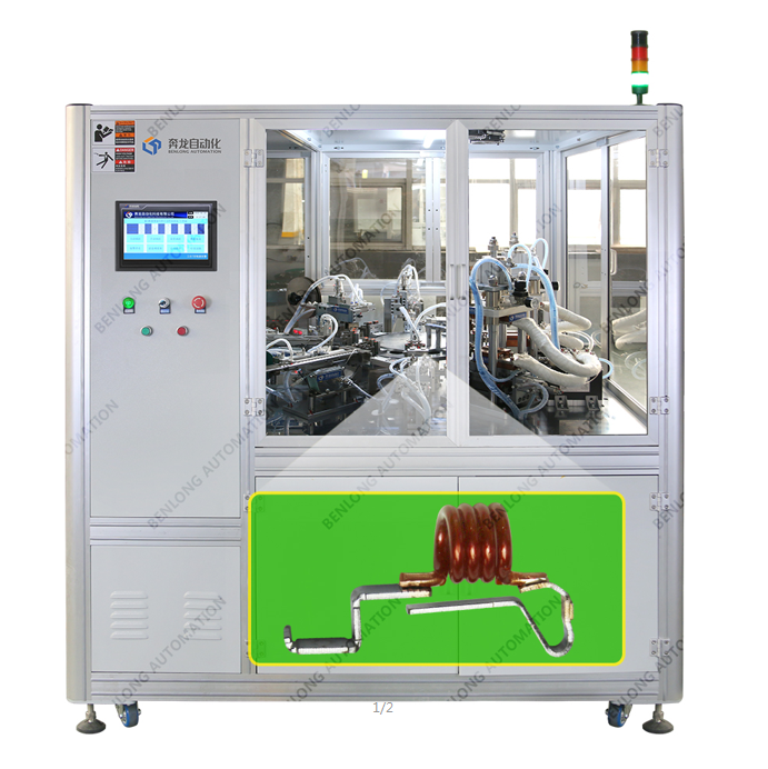
MCB thermal trip set automatic welding line
Custom MCB thermal trip set automatic welding line with robotic cells, vision alignment (±0.05mm), closed‑loop energy control, and full traceability. Supports multiple bimetal sizes. Rapid changeover. For high‑volume production of IEC 60898‑1 compliant thermal trip assemblies.
High‑Precision Automated Welding Line for MCB Thermal Trip Sets
This MCB thermal trip automatic welding line is a modern machine that has been specifically developed for high-precision welds of bimetallic thermal trips used in miniature circuit breakers (MCBs). With the line’s design focusing on high-volume production, it consists of multiple robotic welding cells, real-time monitoring of the welding process, and intelligent quality assurance (QA) systems to ensure that each thermal trip exhibits consistent performance throughout the manufacturing process. High-precision vision alignment systems utilize advanced optical technologies to achieve micrometer-level aligned positioning accuracy. Using closed-loop control, the welding parameters remain at optimal settings during the entire manufacturing run, resulting in consistent weld joint strength, and electrical characteristics required to produce thermal trips that comply with IEC 60898-1.
Custom engineering: 90-120 days | Turnkey integration | Robotic welding + vision alignment

What is an MCB Thermal Trip Set Automatic Welding Line?
A fully automated or semi-automated welding line for MCBs using thermal projected welding technology is a production system that welds bimetallic strips (the component responsible for thermal overload protection) to their support frames and/or current-carrying terminals. The welded bimetallic strip/subassembly is critical to the thermal trip characteristic of MCBs as the weld creates a low resistance electrical connection.
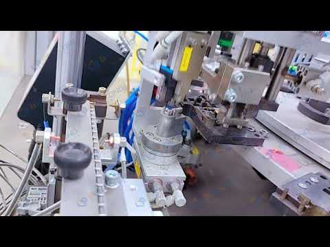
High‑speed, repeatable placement and welding of bimetal to support frame.
Micron‑level positioning ensures correct bimetal location, critical for trip accuracy.
Real‑time energy/force adjustment compensates for electrode wear and part variation.
Designed for your bimetal geometry, support frame, and production targets.
Line Features & Welding Process
Technical Specifications
| Bimetal strip compatibility | Length 10‑40mm, width 3‑15mm, thickness 0.3‑1.2mm (custom tooling for other sizes) |
|---|---|
| Support frame materials | Copper alloy, brass, steel (tin‑plated or bare) |
| Welding technology | Resistance welding (capacitive discharge or inverter DC) with programmable energy/force |
| Positioning accuracy | ±0.05mm (vision‑guided) |
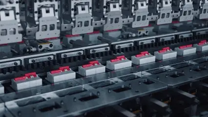
| Typical output (customizable) | Optimized for high‑volume manufacturing – suitable for 10,000+ units per shift |
| Changeover time | Under 30 minutes between product families (recipe + quick‑change tooling) |
| Quality monitoring | In‑process weld energy monitoring, optional post‑weld resistance or pull‑test station |
| Control system | PLC (Siemens/Mitsubishi) with HMI, closed‑loop parameter adjustment, recipe storage |
| Traceability | Barcode or RFID per component; test results linked to serial number |
| Power & air supply | 380V ±10% 50Hz | Compressed air 0.5-0.7MPa |
Core Technical Advantages (Custom Non‑Standard Design)
Micro‑level vision alignment
High‑resolution cameras detect bimetal position and orientation before welding, ensuring consistent joint location even with part variation from stamping.
Closed‑loop energy control
The welding controller monitors voltage, current, and duration for each pulse. If the calculated energy deviates from the target, the controller automatically compensates – eliminating cold welds or excessive splatter.
Quick‑change modular tooling
Pre‑centered welding electrodes and fixturing allow changeover between bimetal sizes in under 30 minutes. Recipes store welding parameters for each product family.
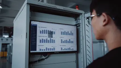
Integrated traceability
Each welded component receives a unique ID (laser‑marked or barcode). The line stores welding parameters, vision check results, and pass/fail decisions for full lifecycle traceability – essential for ISO 9001 and IEC compliance audits.


Customer Success Story (Custom Non‑Standard Line)
One of the largest MCB (Miniature Circuit Breaker) manufacturing companies within Europe had previously completed numerous quantities of bimetal strips through two main methods of production (manual and assembly methods). To further enhance production efficiency and to reduce production cost through automated processes, the European MCB manufacturer required a single production line to produce three different-sized bimetal strips (6A, 20A, 63A) with the shortest possible changeover times (or minimal changeovers). To achieve this objective, Benlong provided a modular thermal trip set welding line with:
Welding line defect levels decreased from an original 0.80% defect rate to a final 0.07% defect rate, allowing the client to create more product to satisfy increased volume requirements without needing any more manual workstations.
Applications and Integration
Custom Engineering & Delivery
Request a Custom Thermal Trip Welding Line Quote
Please provide your bimetallic material samples, drawings of the support frames you need built, and estimated production volumes. Our engineers will create a customized robotic welding solution with complete closed-loop process control and full traceability for your application.
WhatsApp: +86 150 5837 0007 | Email: xsb@benlongkj.cn | English & Chinese support
Why Choose Benlong for Thermal Component Welding?
- 15+ years designing automated welding lines for MCB thermal trip assemblies
- In‑house vision integration and robotic programming
- Closed‑loop energy control for consistent weld quality
- Modular design – expandable for cleaning, marking, or testing
- Global service and spare parts support
Typical Custom Line Includes
Bimetallic feeder · Vision Module for Alignment · Robotic Welding System (Capacitor Discharge or inverter DC) · Closed-loop Weld Controller · Post Weld Quality Verification System (resistance or Pull Tester) · Optional Laser Marking Station · (Programmable Logic Computer) with Operator Interface · Safety Enclosures · 20+ Different Recipe Storage for Product Types · One Set Tooling (for Changing) · 1 Year Warranty.
Frequently Asked Questions
Resistance welding is accomplished through capacitive discharge and inverter DC methods. Capacitive discharge produces quick, high energy “pulse” welds for thin, short bimetal strips, whilst inverter DC has greater control over the weld for thicker materials. Your decision will depend primarily on how thick your bimetal is and what material your support frame is made from.
Every pulse of weld energy (voltage, current, & how long) is monitored by using a closed loop controller. Upon adjusting or rejecting if a deviation from the stored profile occurs. An inline resistive measurement station may be used to directly check the joint resistance as well.
Yes. The vision alignment system can be trained to identify various bimetal shapes through the use of customizable feeding tooling and welding electrodes by product family. Changeover time to different shapes is generally less than thirty (30) minutes.
Normally, the welded thermal trip sets are passed directly to a calibration station and will include conveyor links and data handshake (via ethernet or i/o) to communicate to the calibration bench the weld quality, allowing the automatic rejection of bad parts from entering calibration.
For a new thermal trip design (new bimetal size, support frame, and tooling), lead time is typically 90-120 days (including design, feeder fabrication, vision programming, and commissioning). For minor variants of an existing design, 60-75 days.
Related Products
MCB magnetic trip set automatic welding machine
View Details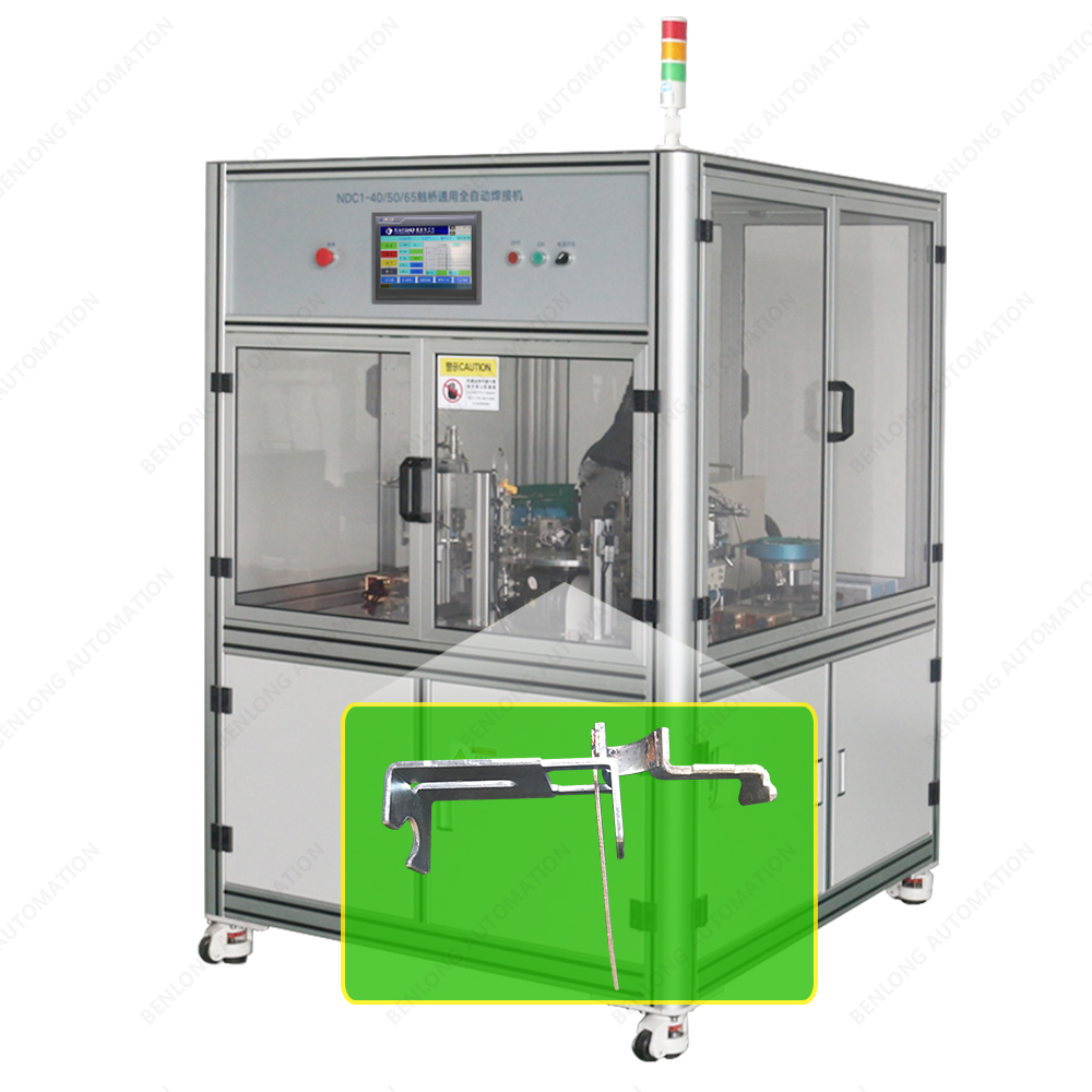
MCB Bi-metal Support Frame automatic welding machine
View Details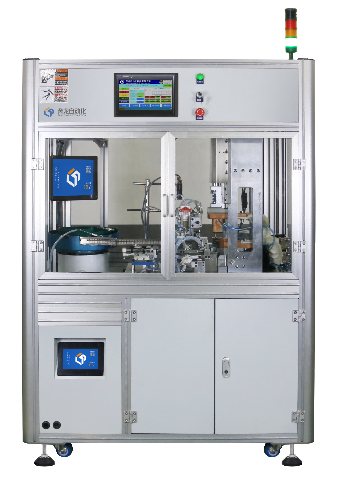
Sliver dot + Contact automatic welding machine
View Details
RCBO PCBA automatic soldering machine
View Details