benlong


میز تست تماس کمکی و سیگنال
میز تست کنتاکت کمکی و سیگنال برای RCBO/MCB. تست منطق دوحالته (کمکی و هشدار)، مقاومت کنتاکت (<50 میلیاوم، و استحکام دیالکتریک (1500V/2000V). هشدارهای کاذب را از بین میبرد، اکسیداسیون را تشخیص میدهد، یکپارچگی عایق را تضمین میکند. ایدهآل برای آزمایشگاههای کنترل کیفیت و خطوط تولید. مطابق با IEC 60947-5-1.
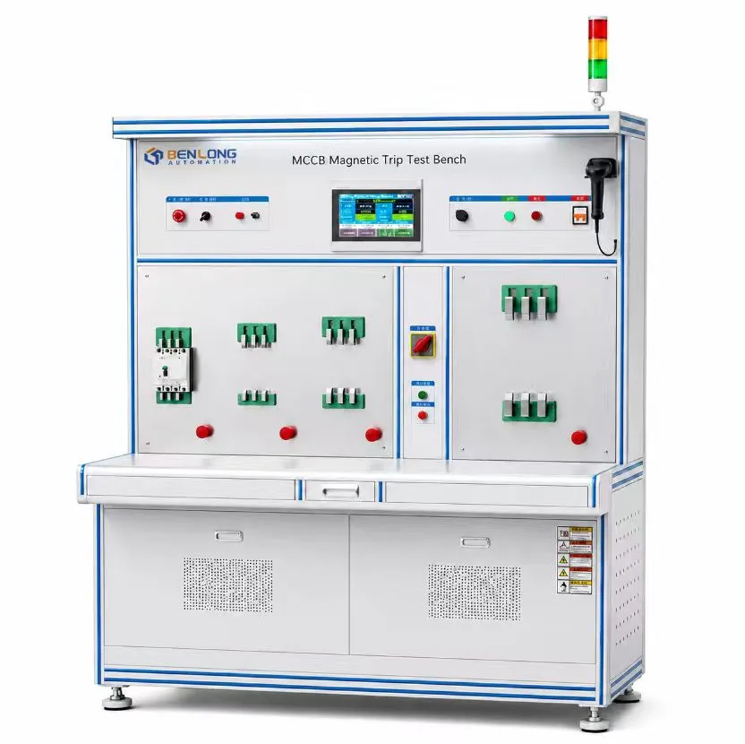
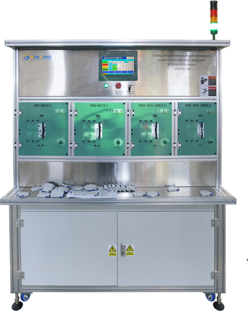
میز تست تماس کمکی و سیگنال برای RCBO/MCB
آزمایش خودکار و دستی کنتاکتهای کمکی و کنتاکتهای هشدار (یا سیگنالها) روی میز آزمایش انجام میشود. میز آزمایش تأیید میکند که وضعیت تماس از حالت عادی به معکوس (یا بالعکس) تغییر میکند هر بار که دسته کلید دستی باز یا بسته میشود (تأیید وضعیت تماس کمکی برای هر بار که شخص دسته کلید را دستی باز یا بسته میکند). دستگاه آزمون تأیید میکند که وضعیت کنتاکت هنگام باز شدن دستی کلید (تأیید وضعیت کنتاکت هشدار در حین باز کردن دستی کلید توسط شخص) تغییر نخواهد کرد و یا با وقوع خطا تغییر نخواهد کرد، اما هنگام شبیهسازی قطع به دلیل خطا، وضعیت آن تغییر خواهد کرد. (این شبیهسازی یا با دکمه تست RCBO یا با ایجاد یک اتصال کوتاه موضعی انجام میشود.) این دستگاه همچنین مقاومت کنتاکت کمکی را با استفاده از یک میکرو اهممتر اندازهگیری کرده و آزمایش ولتاژ بالا (hi-pot) را برای تأیید عدم وجود جریان نشتی انجام میدهد. این دستگاه برای آزمایشگاههای کنترل کیفیت (QC) و خطوط تولید، و همچنین بازرسی ورودی ماژول کنتاکت کمکی مناسب است.
تحویل استاندارد: ۳۰–۴۵ روز | تست منطق دوحالته | مقاومت تماس و تست ولتاژ بالا

این میز تست چه مشکلاتی را حل میکند؟
تماسهای کمکی/سیگنال هنگام انجام نظارت از راه دور بر کلیدهای اتوماتیک، اجزای ضروری هستند. با این حال، سه مشکل عمده وجود دارد که برای تولیدکنندگان و کاربران کلیدهای اتوماتیک مشترک است: منطق سوئیچینگ نادرست (مثلاً فعال شدن هشدار در هنگام باز کردن دستی، که منجر به هشدارهای کاذب میشود)؛ مقاومت بالای تماس (اکسیداسیون تماسها منجر به از دست رفتن انتقال سیگنال میشود)؛ و شکست عایق (این میتواند یک مشکل ایمنی ایجاد کند). این بنچ با یک توالی آزمایششده، منطق دوحالته (کمکی در مقابل هشدار) را اعتبارسنجی کرده و مقاومت تماس را (برای شناسایی فیوزهای قطعشده) اندازهگیری میکند.
حالت کمکی تست (تماسها با دستگیره تغییر میکنند) و حالت هشدار (تماسها فقط هنگام قطع بهدلیل خطا تغییر میکنند و نه هنگام باز کردن دستی).
مقاومت تماسهای بسته را اندازهگیری میکند (معمولاً کمتر از ۵۰ میلیاوم) – اکسیداسیون یا تماس ضعیف را که میتواند باعث خرابی سیگنال شود، تشخیص میدهد.
برای بررسی یکپارچگی عایق، مطابق با IEC 60947-5-1، ولتاژ 1500 ولت یا 2000 ولت جریان متناوب بین ترمینالها اعمال میشود.
بررسی تناسب و عملکرد صحیح تماس کمکی/سیگنال هنگام نصب روی RCBO/MCB.
فرآیند آزمون و مزایای مشتری

مشخصات فنی
| توابع تست | منطق حالت کمکی، منطق حالت هشدار، مقاومت تماس، استحکام دیالکتریک (هیپات)، قفل مکانیکی |
|---|---|
| اندازهگیری مقاومت تماس | دامنه ۰–۲۰۰ میلیاوم، دقت ±۱۱ تیپیاستی، جریان آزمون ۱ آمپر جریان مستقیم (میکرو اهمسنج) |
| پذیرش مقاومت تماس | <۵۰ میلیاُهم (معمولی)، حد قابل برنامهریزی |
| ولتاژ تست با ولتاژ بالا | ۱۵۰۰ ولت AC / ۲۰۰۰ ولت AC (قابل برنامهریزی، ۱ تا ۶۰ ثانیه) |
| آستانه جریان نشت | قابل برنامهریزی (مثلاً ۵ میلیآمپر، ۱۰ میلیآمپر) |
| آزمایش حالت کمکی | عملیات دستی با دستگیره (بستن/باز کردن) – بررسی خودکار تداوم تماسهای NO/NC |
| آزمایش حالت هشدار – باز کردن دستی | تماس نباید حالت خود را تغییر دهد. |
| آزمایش حالت هشدار – شبیهسازی قطع خطا | تماس باید فوراً وضعیت خود را تغییر دهد (NO→بسته، NC→باز) |
| روش شبیهسازی قطع خطا | برای RCBO: فشردن خودکار دکمه “T”؛ برای MCB: تزریق جریان اتصال کوتاه (اختیاری) |
| منبع تغذیه | ۲۲۰ ولت ±۱۰٪، ۳ فاز، ۵۰ هرتز |
مزایای اصلی برای مشتری – چرا تولیدکنندگان از این نیمکت استفاده میکنند
مزیت ۱: حذف هشدارهای کاذب در میدان
تماسهای هشدار تنها زمانی به درستی (یعنی به عنوان تماسهای هشدار) آزمایش میشوند که یک خطای واقعی رخ دهد (مثلاً فشردن دکمه تست RCBO یا شبیهسازی یک اتصال کوتاه). همچنین هنگامی که کلید مینیاتوری بهصورت دستی باز میشود، بدون ایجاد هشدار کاذب، بهدرستی آزمایش خواهند شد که این امر به حذف منابع هدررفته برای رفع هشدارهای کاذبی کمک میکند که باعث ایجاد تردید در مشتریان دربارهٔ قابلیت اطمینان تجهیزاتشان میشوند.
مزیت ۲: اکسیداسیون تماس را قبل از آنکه باعث خرابی شود، تشخیص میدهد.
بازگشتهای میدانی و تماسهای خدماتی برای تولیدکنندگان پرهزینه است؛ اندازهگیری مقاومت تماس بالا (۵۰ میلیاوم) باعث نوسان یا قطع سیگنال میشود. تولیدکنندگان این سیگنال متناوب را ضبط کرده و قبل از فراخوانی مجدد به مرکز خدمات، تجهیزات را تعمیر میکنند.
مزیت ۳: تضمین یکپارچگی عایق برای ایمنی
آزمون استحکام دیالکتریک با اعمال ولتاژ بالا (۱۵۰۰ ولت یا ۲۰۰۰ ولت) بین ترمینالها و بررسی خرابی عایق و همچنین جریان نشت انجام میشود. در نتیجه، آزمون استحکام دیالکتریک بهویژه برای دستگاههایی که دارای کنتاکتهای کمکی هستند و به PLCهای ولتاژ پایین یا مدارهای کنترل متصل میشوند، اهمیت دارد، زیرا هرگونه نقص در ماده عایق میتواند منجر به آسیب به تجهیزات اتوماسیون بسیار گرانقیمت یا ایجاد خطر شوک الکتریکی شود.
مزیت ۴: آزمایش سریع و قابل تکرار
با خودکارسازی توالی تست منطقی دوحالته، آزمایشهای روی میز اکنون میتوانند تأیید/آزمایش یک ماژول کنتاکت کمکی را در کمتر از ۳۰ ثانیه به پایان برسانند، در حالی که تست دستی با مولتیمتر چندین دقیقه طول میکشد. یک اپراتور میتواند در طول یک شیفت صدها ماژول از این نوع را آزمایش کند و نتایج قابل تکرار با دقت 100% سازگار خواهند بود.


موفقیت مشتری – حذف بازگشتهای هشدار کاذب
یک شرکت معتبر RCBO، ۵۱ TP3T از بازخوردهای میدانی خود را به ماژولهای تماس کمکی اختصاص داده بود و این ماژولها هنگام باز شدن دستی سیستم، هشدارهای کاذب تولید میکردند. این شرکت علت این مشکلات را بررسی کرد و دریافت که منبع مشکل، آزمون ناسازگار منطق در حین تولید بوده است. سپس آنها یک میز آزمون تماس کمکی و سیگنال با آزمون خودکار دوحالته برای تأیید منطق معرفی کردند و به دستاوردهای زیر رسیدند:
این دستگاه آزمایشگاهی ظرف چهار ماه پس از خرید، هزینههای خود را جبران کرد و علاوه بر آن، بهعنوان مرکز آزمون برتر برای هر قطعهٔ کنتاکت کمکی تولیدشده شناخته شد.
کاربردها – جایی که این نیمکت بیشترین ارزش را ایجاد میکند
مهندسی سفارشی و تحویل
درخواست ارائه قیمت برای بنچ تست کنتاکت کمکی سفارشی
لطفاً مشخصات و نمونههای آزمون تماس کمکی/سیگنال را ارائه دهید. ما یک دستگاه آزمون طراحی خواهیم کرد که دارای حالت دوگانه، مقاومت تماس (سطح پایین) و آزمون ولتاژ عایقی بالا (hi-pot) است و بازگشت سرمایه (ROI) را محاسبه خواهیم کرد.
واتساپ: +86 150 5837 0007 | ایمیل: xsb@benlongkj.cn | پشتیبانی انگلیسی و چینی
چرا برای بنچهای تست تماس از بنلونگ استفاده کنیم؟
- ۱۵+ سال سابقه طراحی تجهیزات آزمون تماس برای قطعات الکتریکی کمولتاژ
- آزمون منطقی دوحالته اثباتشده (کمکی در مقابل هشدار) – هشدارهای کاذب را از بین میبرد
- اندازهگیری یکپارچه مقاومت تماس (دقت ±۱۱TP3T) و تست هایپات
- محل قرارگیری جهانی برای چندین مدل کنتاکت کمکی
- خدمات جهانی و پشتیبانی قطعات یدکی
نیمکت استاندارد شامل
دستگاه همهمنظوره تماس سیگنال کمکی، با عملکرد خودکار دستگیره در حالت کمکی، شبیهساز قطع بهدلیل خطا و/یا فعالکننده دکمه تست برای تزریق اتصال کوتاه. میکرو اهممتر برای اندازهگیری مقاومت تماس. تستکننده AC پتانسیل بالا برای ۲۰۰۰ ولت. PLC با رابط کاربری HMI. چراغهای نشانگر OK/NG. محفظه ایمنی. دفترچههای راهنمای کاربر. گواهیهای کالیبراسیون. ضمانت یکساله.
سوالات متداول
تماسها در حالت کمکی با هر بار عمل کردن دستهی کلید اتوماتیک وضعیت خود را تغییر میدهند، چه در حالت عملکرد دستی (مانند باز یا بسته کردن) بهعنوان نشانگر از راه دور موقعیت؛ آنها بهدلیل یک رویداد قطع (خطا)، مانند اضافهبار یا اتصال کوتاه، وضعیت خود را تغییر نمیدهند. تماسهایی که در حالت هشدار استفاده میشوند، وضعیت کلید قطعکن را هنگام عملکرد ناشی از خطا (مانند اضافهبار یا اتصال کوتاه) نشان میدهند. هدف از آزمون میز آزمایشی در هر دو حالت، تأیید عملکرد مورد انتظار این تماسها است.
در مورد RCBOها، نیازی به ایجاد مدار تست نیست زیرا دستگاه تست بهطور خودکار با فشردن دکمه T (test) واقع در روی پوشش کلید خودکار، آزمایش را انجام میدهد. در مورد کلیدهای مینیاتوری (MCB)، ممکن است بنچ یک جریان کوتاهمدت قابل تنظیم تزریق کند تا محدودهای برای عملکرد مکانیزم قطع مغناطیسی ایجاد شود، یا استفاده از یک محرک مکانیکی برای فعال کردن مکانیزم نیز نیازمند ایجاد یک مدار تست خواهد بود. تغییر وضعیت تماس بهصورت بلادرنگ تأیید میشود.
IEC 60947-5-1 برای کنتاکتهای جدید مقاومت کمتر از ۵۰ میلیاوم را توصیه میکند. این بنچ به شما امکان میدهد یک حد بالایی قابل برنامهریزی (مثلاً ۵۰ میلیاوم) تنظیم کنید. مقاومت بالاتر نشاندهنده اکسیداسیون، آلودگی یا فشار تماس ناکافی است که میتواند منجر به انتقال سیگنال متناوب شود.
بله. روی پایهٔ جهانی پروبهایی وجود دارد که میتوان آنها را برای سازگاری با پیکربندیهای مختلف پین تنظیم کرد. پس از انتخاب دستور محصول، توالی تست پیکربندی پین را برای شما تعیین میکند.
تست بنچ پیوستگی کنتاکتهای NO و NC را در تمام مراحل توالی تست بررسی میکند. در تست کمکی باید هنگام قرار داشتن کلید در وضعیت روشن، پیوستگی از طریق کنتاکت NO برقرار باشد و هنگام قرار داشتن کلید در وضعیت خاموش، پیوستگی از طریق کنتاکت NC برقرار باشد. حالت هشدار بررسی میکند که تنها کنتاکت مناسب هنگام وقوع قطع ناشی از خطا وضعیت خود را تغییر دهد.
محصولات مرتبط

میز تست جریان حلقه مغناطیسی
مشاهده جزئیات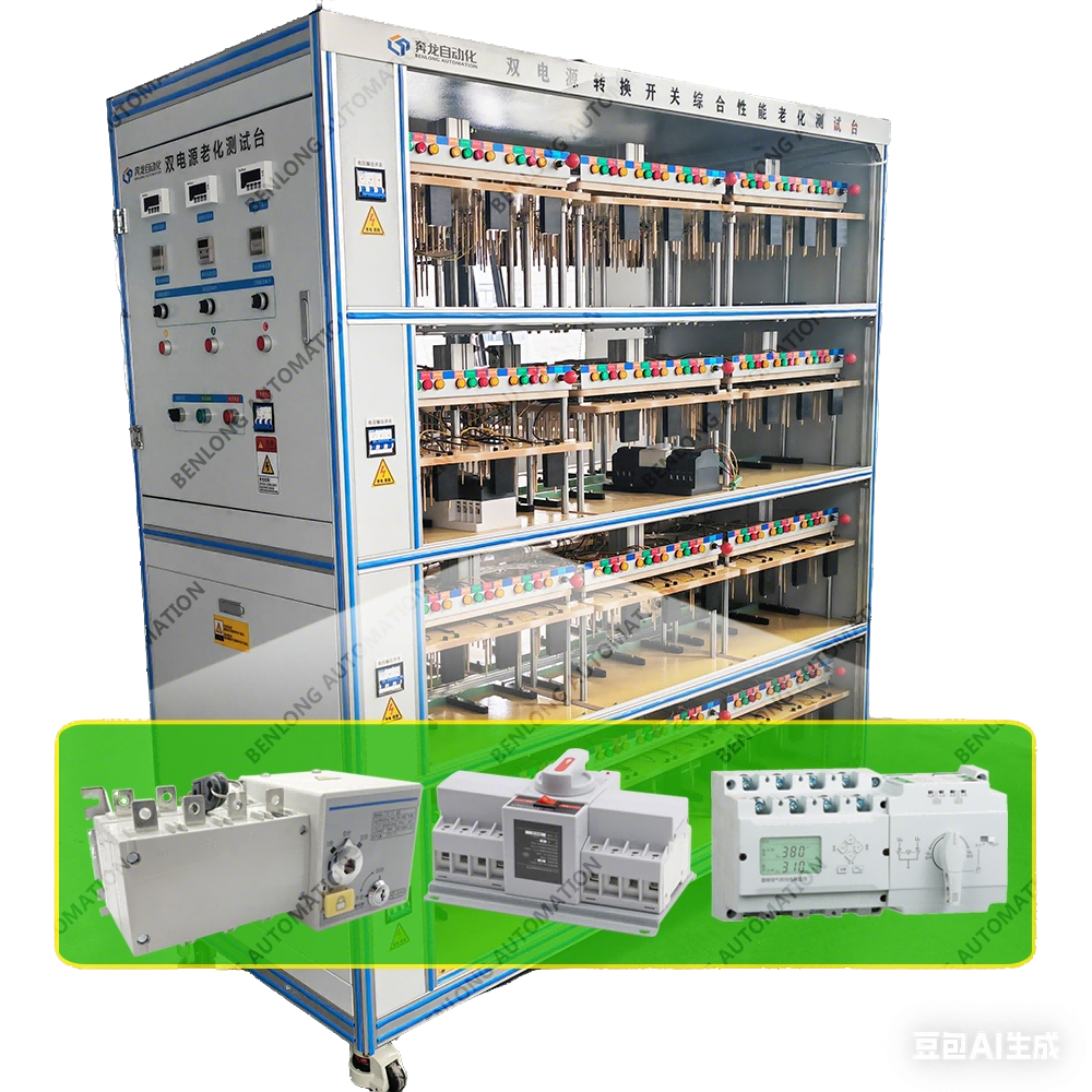
میز تست پیری ATS
مشاهده جزئیات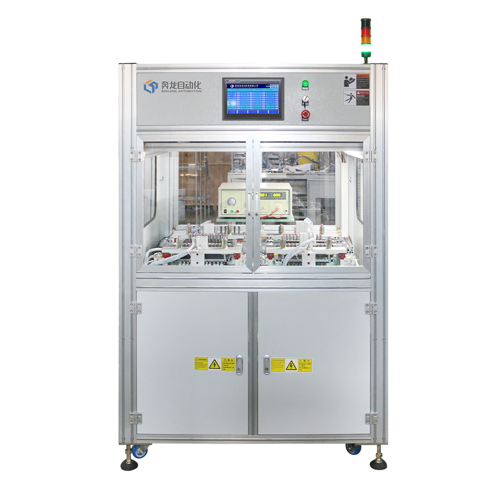
تست تریپ مغناطیسی خودکار MCB + دستگاه تست روشن خاموش و ولتاژ بالا
مشاهده جزئیات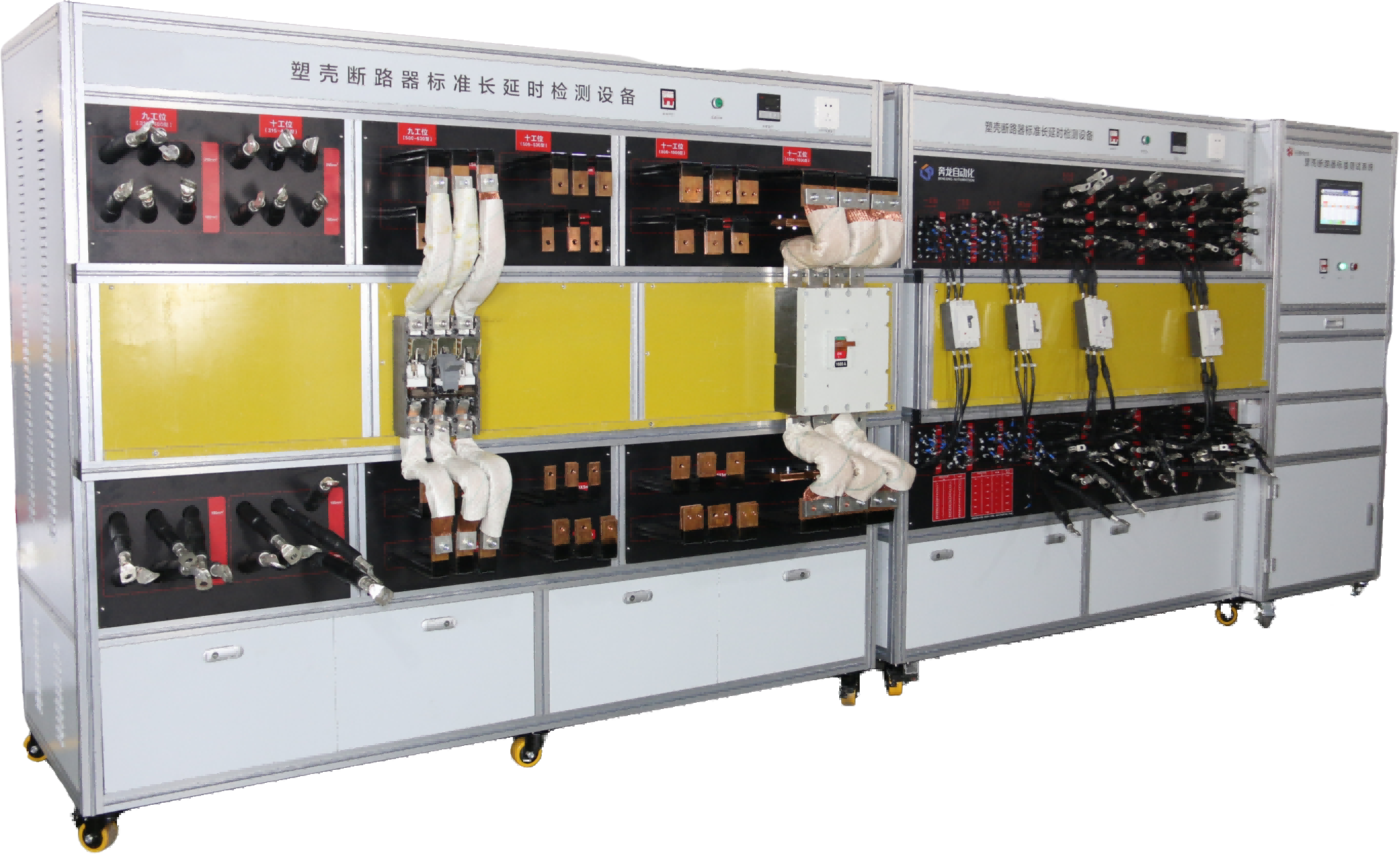
میز کالیبراسیون حرارتی طولانی مدت MCCB
مشاهده جزئیات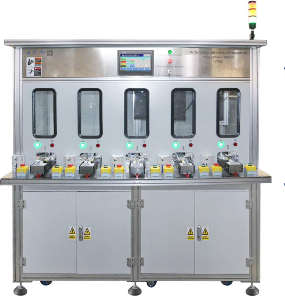
میز تست جامع نیمه اتوماتیک RCBO
مشاهده جزئیات