benlong



What Is Hi-Pot Testing?
Regarding the Power supply systems, electrical motors, transformers, and electric car charging stations, they undergo a testing process called “hi-pot test” before leaving the production facility. Not many buyers might be aware of what hi-pot test consists of, so we will clarify what it actually means. Hi-pot is short for high potential test, which, in its basic meaning, is another title for dielectric withstand testing. In other words, it implies applying the voltage considerably higher than the used voltage of the product, and checking whether the insulation can hold that voltage or not.
In a high voltage or dielectric withstand testing procedure, electrical insulation and high voltage are tested for 60 seconds. The test is conducted with the application of very high voltage ranging between 1,000 – 3,000 volts A. C. or between 1,500 – 4,200 volts D. C. The process involves sending current between the live part of the tested product and grounded surfaces or surfaces within the product. The current flow through the insulation is monitored. The test is believed to confirm whether insulation under testing is capable of surviving excessive high voltage spikes without causing failures of insulation.
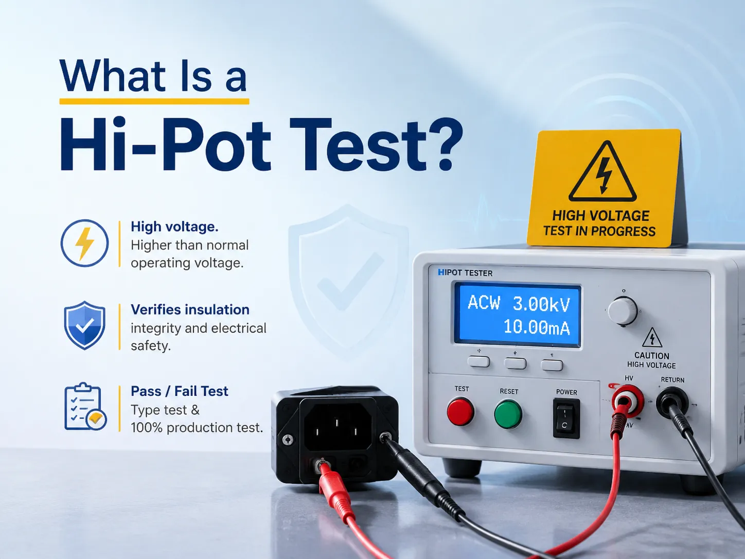
What Is a Hi-Pot Test?
A hi-pot test refers to the high-potential electrical safety examination, which assesses the practical voltage exceeding the normal operating voltage of the device’s insulation system. The initial stage of the examination consists in determining whether the insulation is capable of preventing the flow of electrical current from energized electrical circuits onto any surfaces, like a chassis or other conductors. The term itself traces its origin to “high potential” — which reflects the high voltage used during the process of testing.
Why is it necessary to conduct a test at a voltage higher than the one specified during the manufacture of electrical equipment? The thing is that electricity creates all sorts of disturbances — e.g. lightening, switching, and grid faults, which lead to short spikes of voltage several times exceeding the specific standard voltage. Thus, the insulation which passes the hi-pot test at that point may possess certain manufacturing imperfections like manufacturing defects or damage incurred during insulation manufacturing. Thus, conducting the hi-pot electrical examination means creating a certain excessive voltage and verifying that the insulation holds, which means eliminating the defects at a stage preceding the product’s appearance on the market.
The hi-pot test is a so-called pass-fail test that does not allocate any points and which is used during the device testing and manufacturing stages to ensure the safety of the final product.
How It Works: The Principle
The basic idea is to apply high voltage across two points which should be isolated, and then measure the leaking current flowing through the insulation. The two points can be any of the following:
- Power input and ground
- Primary and secondary circuits
- Circuit and chassis or exposed metallic part
- Power and ground planes in a printed circuit board
The entire testing process consists of four stages:
- Ramp-up: starting at zero voltage, the voltage gradually increases to the target voltage in a controlled ramp (usually, this process lasts until the first part of the test but, also, may proceed instantly (when testing manufacturing devices).
- Holding: voltage remains constant for the desired duration – that means 60 seconds for the appliaince test; while for device testing it will be from 1 to 2 seconds at higher voltage of 20%.
- Monitoring: during the holding process the device constantly monitors leakage current in the isolation. Perfect isolation means that the voltage does not pass any leakage current; while damaged isolation uses too much currentation or completely fails.
- Decision-making: if the leakage current does not exceed the limit and no breakdown occurs, the product is considered to be correct in the opposite case the product is considered defective.
In terms of physical reproduction, the test subjects insulations to an electric force. As a result, if there is a pinhole, thin section, contamination, or incorrect creepage distance in insulations, the electrical force will discover the area of weakness and start flowing through it.
Standards and When They Apply
| Standard | Covers | Typical Test Voltage (230V product, basic insulation) |
|---|---|---|
| IEC 60950-1 (withdrawn Dec 2020, replaced by IEC 62368-1) | IT and telecom equipment (legacy) | ~1,500V AC (2×U + 1,000V) |
| IEC 62368-1 | Audio/video, IT, communication equipment — the current standard | 1,500V AC basic / 2,500V AC reinforced |
| IEC 60601-1 | Medical electrical equipment | ~1,800V AC basic (2×U ×1.414 + 1,500V style) |
| IEC 61010-1 | Measurement, control, and lab equipment | 2U + 1,000V |
| UL 61010 / UL 62368 | North American adoptions of the above | 1,250V AC or 1,500V DC fixed values common |
| ISO 16750-2 | Automotive electrical equipment | 500-1,000V DC, leakage ≤1mA |
| IEC 60204-1 | Industrial machinery electrical equipment | 2U + 1,000V (min 1,000V) |
For the readers in the majority, the standards that count include IEC 62368-1 (consumer electronics, IT), IEC 60601-1 (medical), IEC 61010-1 (lab/industrial measurement), and IEC 60204-1 (machinery — this standard is exclusively related to manufacturing processes such as automated testing stations for MCB). If you build electrical machinery or test equipment, understanding these tests is part of the acceptance criteria — the same discipline that governs automated testing in our automated vs manual testing analysis.
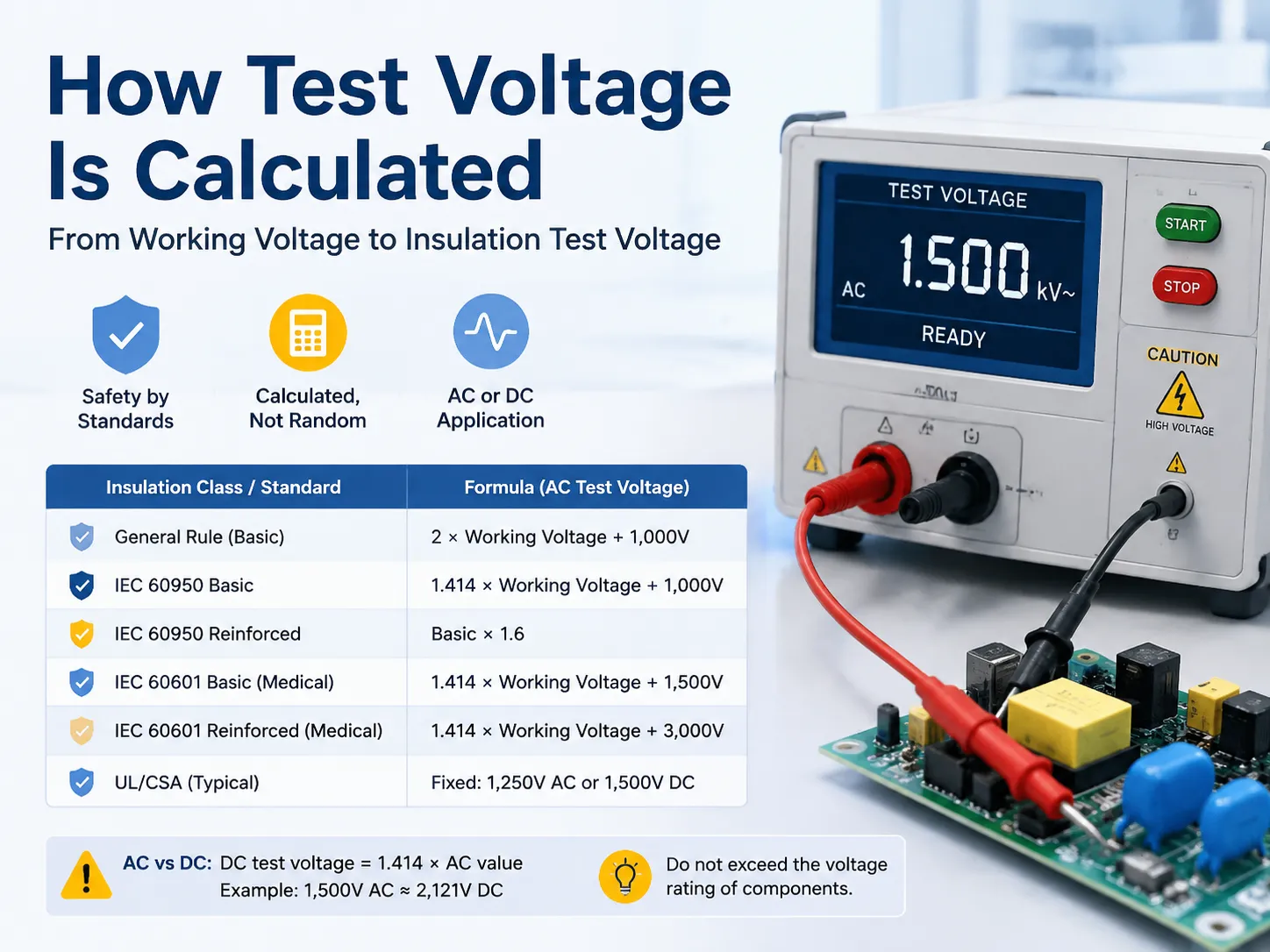
How Test Voltage Is Calculated
The voltage applied during the test is not arbitrary, as it corresponds with standard formulas relating to the working voltage (the maximum root mean square (RMS) voltage present in the insulation during standard operation) and insulation grade:
| Standard / Insulation Class | Formula | Example (230V working) |
|---|---|---|
| General rule (basic) | 2 × working voltage + 1,000V | 2×230 + 1,000 = 1,460V → 1,500V AC |
| IEC 60950 basic (AC peak basis) | 1.414 × working + 1,000V | 1.414×230 + 1,000 ≈ 1,325V → 1,500V AC |
| IEC 60950 reinforced | Basic × 1.6 | 1,500 × 1.6 = 2,400V → 2,500V AC |
| IEC 60601 basic (medical) | 1.414 × working + 1,500V | 1.414×230 + 1,500 ≈ 1,825V AC |
| IEC 60601 reinforced (medical) | 1.414 × working + 3,000V | ≈ 3,325V AC |
| UL/CSA fixed values | Fixed per product class | 1,250V AC or 1,500V DC common |
AC with respect to DC testing voltage: when applying a DC voltage to match the peak value of AC voltage, it is necessary to use the factor of √2 — e.g. 1,500V AC corresponds to approximately 2,121V DC. DC is used more frequently in the production line processes because of its simplicity in operation when there are large capacitive loads in the line; AC is used for regulatory testing because of its ability to test the insulation in both positive and negative polarities similar to real conditions.
It has to be remembered that the testing voltage should never exceed the voltage rating of parts of the circuit like Y-capacitors or optocouplers, etc. as they may fail in the process.
Pass/Fail Criteria: What Counts as a Passing Reading?
A hi-pot test passes when no breakdown occurs and leakage current stays below the standard’s limit. Typical limits:
| Application / Standard | Leakage Current Limit |
|---|---|
| IEC 60950 / 62368 basic insulation | ≤3.5mA (AC) or ≤2mA (DC) |
| IEC 60950 / 62368 reinforced insulation | ≤0.25mA |
| IEC 60601 medical (BF-type, normal) | ≤0.1mA |
| IEC 60601 medical (single fault) | ≤0.5mA |
| ISO 16750 automotive | ≤1mA (500-1,000V DC) |
| Factory in-house limits | Often 50-80% of the standard (safety margin) |
The following are 3 indications of a failure:
- Spike of leakage currents- the current may be measured from microamps to milliamps.
- Failure of test voltage- being an open circuit, the insulation is no longer intact and becomes conductive.
- Presence of a visual or acoustic signs, such as sparks, smoke, or sudden noise.
It is necessary to explain clearly the important difference between small, stable capacitive leakage current that occurs gradually (with stabilization during ramping) and breakdown which happens suddenly. Typical readings for such devices indicate microamp to low milliamp values — this means they are much below the threshold level and the instrument shows stable readings during the holding time.
Hi-Pot Tester vs Megger: What’s the Difference?
These two instruments are constantly confused, but they measure different things:
| Feature | Megger (Insulation Resistance Tester) | Hi-Pot Tester |
|---|---|---|
| What it measures | Insulation resistance in megohms (MΩ) | Leakage current at high voltage, and withstand capability |
| Typical voltage | 250-1,000V DC | 1,000-10,000V+ AC or DC |
| Result | A resistance reading (higher = better) | Pass/fail against a current limit |
| Typical use | Field/maintenance assessment of insulation quality | Factory safety testing and type testing |
| Stress level | Low; safe for routine checks | High; deliberately stresses insulation to its limit |
| Power source | Often battery-powered | Almost always mains-powered |
To look at this simply, a megger indicates how effective insulation is (a resistance that can be monitored over time) while a hi-pot tester shows whether insulation is good enough to withstand specific overvoltage (pass/fail). With manufacturing, hi-pot testing is the mandatory safety test while maintenance relies on megger tests — both are components of a complete insulation testing process.
Types of Hi-Pot Tests and Applications
- AC hi-pot testing: the standard for type tests — involves constant stressing of insulation in two polarities, which is the closest to practice.
- DC hi-pot testing: widely used on production lines, it is faster than AC hi-pot and does not create reactive current during the process; however, it stresses all insulation only in one polarity.
- Type test (certification): involves the test at the standard voltage during sixty seconds for the samples representative for the product being certified.
- Routine test: needs to be done for every unit for 1-2 seconds, testing at an approximately 20% higher voltage in order to eliminate manufacturing faults (solder leaks, pinched wires, etc.) without slowing down the line.
This technology is applied in power supplies and adapters, home appliances, motors, and pumps, transformers, medical devices and devices of electric vehicles, industrial machines panels, printed circuit boards assemblages, connectors, cables, and lighting products.In the manufacturing world, hi-pot testing is a standard station on automated assembly and test lines — the same kind of integrated test equipment used in breaker production, covered in our automated circuit breaker manufacturing overview, alongside the breaker testing guide for the low-voltage side of the same quality system.
Equipment and Tools
The hi-pot test setup requires the following items:
- Hi-pot tester (dielectric withstand tester): it is the system which provides the potential required for testing and quantifies any leakage. One should look for a model which can provide output voltage of at least the double of the working voltage of the device being tested. Most of the tests are performed at 5kV and above.
- Test leads and fixtures: the leads must be rated for high voltage; besides that an insulated charger must be present.
- Safety: the system must have a two-hand start mechanism and a safety grounding link.
- Discharge system: it is necessary for DC testers to dissipate the device’s charge after the test.
- Calibration: it is essential that the testers are regularly calibrated.
Test Procedure Step by Step
- Make the DUT free from power sources and discharge it – separate from the network and drain capacities to ensure a reading of zero residual voltage left on the device.
- Connect the tester – one terminal to the chassis, and the second one to the power circuit (often there is a socket for such connection in the tester).
- Program the device settings – the amount of the applied voltage (by using standard engineering formula), the time of the measurement (min 60 seconds for 60-second tests, 1-2 seconds for devices), the limit of acceptable leakage, and the speed of the voltage rising.
- If you are going to perform DC testing, make sure to select the necessary value of discharging time.
- Carry out the control: the voltage increases, holds and the device measures the leakage current. Store the result.
- Document: manufacturing line saves every production run history based on the same data-driven evaluation system implemented with automatic line design.
When testing for the first time, one must assess them on at least one known good sample, as well as one bad sample to independently verify test failure — if a tester never reports a faulty output, then it is unreliable.
Why Would a Hi-Pot Test Fail?
| Cause | Symptom | Fix |
|---|---|---|
| Solder splash / conductive contamination on PCB | Leakage spikes at test voltage | Improve cleaning; verify wave-solder process |
| Pinched or damaged wire insulation | Breakdown at the damaged point | Inspect wire routing; fix assembly |
| Wrong creepage/clearance distances | Arcing across the gap | Design review per the standard’s spacing tables |
| Component with lower voltage rating (e.g., Y-cap) | Component fails before insulation | Disconnect component per standard, or redesign |
| Moisture / humidity in the product | Leakage higher than normal | Control manufacturing environment; dry before test |
| Defective transformer/motor winding insulation | Breakdown at winding | Supplier quality control; incoming inspection |
| Tester misconfiguration | False failures (voltage too high, limit too low) | Verify settings against the standard; calibrate tester |
For the manufacturing department, a hi-pot failure is a fortunate occurrence – it detects a defect property of the product. The engineering department’s response should be to address the root cause of the problem rather than adjust the testing process.
Safety and Best Practices
- Always consider a hi-pot test station as dangerous. It generates thousands of volts and can transmit dangerous current. Such equipment can only be used by skilled individuals.
- Be sure to utilize interlocks: two-hand operation and safety enclosure interlocks, as well as visible alarm signals on test devices.
- Do not touch the DUTs during a test and discharge DC-tested devices before dealing with them.
- Be sure to ground everything correctly: test apparatus, testing fixture and work area of the operator.
- Avoid humid conditions (40-60% RH is recommended) in order to rule out wrong defects coming from moisture influence.
- Make sure to calibrate hi-pot test apparatus at least once a year and check it with reference points.
- It is important to save the results of tests along with the serial numbers of equipment in order to be able to follow the course of a testing process.
- Be sure to include in your document test specifications such as voltage, duration, the limits of measurement and the corresponding standard.
Frequently Asked Questions
What is a passing reading for a HI POT test?
A hi-pot test can be regarded as successful as long as no breakdown happens and the leakage current doesn’t exceed the acceptable limit during the entire testing period — that is, up to 3.5mA (AC) or 2mA (DC) for basic insulation according to IEC 60950/62368 standards, up to 0.25mA for reinforced insulation, up to 0.1mA for medical equipment with BF-type insulation according to the IEC 60601 standard, and up to 1mA for automotive equipment according to the ISO 16750 standard. In real life, the majority of good products demonstrate a much lower figure (in terms of microamps) with a steady value, thus giving no indication of the breakdown.
What is the difference between a megger and a hipot?
The megger measures insulation resistance in megohms at low DC voltage (250–1,000V) — a value that is gaining popularity in the field and maintenance activities. The hi-pot tester operates at high voltages (1,000V and greater) and measures leakage current relative to a pass/fail threshold. In short, megger = how effective the insulation is; hi-pot = whether it can withstand the overvoltage.
Why would a hipot test fail?
A hi-pot failure occurs when current leakage is exceeded or the insulation is damaged, most often due to: solder or conductive dirt on the PCB, pinched wires or damaged insulation, insufficient distance of creepage/clearance, components (such as Y capacitors) having the threshold voltage lower than the voltage of the test, water in the product, or damaged transformer/motor winding insulation. Improper tester configuration (very high voltage or very low limits) may also result in improper results — always verify configuration against the standard.
What is another name for the hipot test?
The hi-pot test is also known as the dielectric withstand test (the technical term used in various standards), the high-voltage test, the high-potential test, and was historically called the flash test or the pressure test. “Hi-pot” is a casual term used in the industry to refer to the high-potential and the same method with different names in the manuals, standards, and conversations at the production.
References
- Vitrek — IEC 60950 hipot testing requirements and setup
- Capel — What is a hi-pot test (voltage formulas, leakage limits)
- HiPot Tester — Hipot tester insulation testing guide
- JC PCBA — Hi-Pot leakage current limits and breakdown judgment
- IEC 60950-1 / IEC 62368-1 / IEC 60601-1 — safety standards
- UL & IEEE — dielectric withstand test requirements
Conclusion
Hi-pot testing refers to a procedure whereby an electrically powered piece of equipment undergoes a test before it can be declared safe; the technique involves passing a very high voltage through insulation in order to gauge the leakage current that indicates whether the insulation is doing its job. The formulas can be expressed as follows: the operational voltage multiplied by 2, plus 1kg of voltage that relates to basic insulation as per requirements, multiplied by 1.6kg for reinforced insulation under the same guidelines, and even more strictly for medical devices; if the equipment passes the test, it means that no failures were detected during the testing.
Hi-pot test and some other processes involved in the course of production process are important for manufacturers since all units made undergo testing in just a couple of seconds and all problems are identified: solder drop, short wire, or improper interval. Hi-pot test is, however, something that should be known only by engineers and buyers as they should know the hi-pot test and mega test so that the results can be read correctly and accepted properly.That is the thinking behind modern automated production solutions: safety testing done right, every unit, every time.