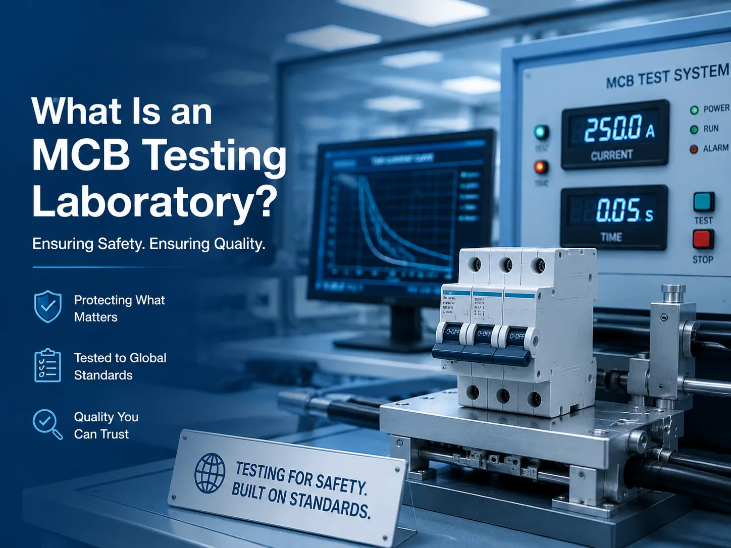
Benlong


So prüfen Sie ein Wechselstrom-Schütz
A Phoenix HVAC technician was called out to evaluate an AC unit that would run for 10 minutes and stop. A visual inspection of the AC unit’s components revealed nothing wrong with its thermostat nor with the breakers. Using a multimeter to measure voltage at the AC contactor in the outdoor condensing unit, the technician quickly diagnosed the problem. Although the contactor coil was being energized, it was only supplying intermittent voltage to the compressor due to the contacts trending open from excessive heat. The contactor was chattering and heating up under load; therefore, the compressor internal thermal overload was turning the compressor off to protect from excessive heat. The technician had the diagnosis so quickly due to his knowledge of what voltages to expect at each terminal (and what abnormal values look like). This article provides a guide to testing sequences — a key difference between a “parts-changer” and a “diagnostician.”
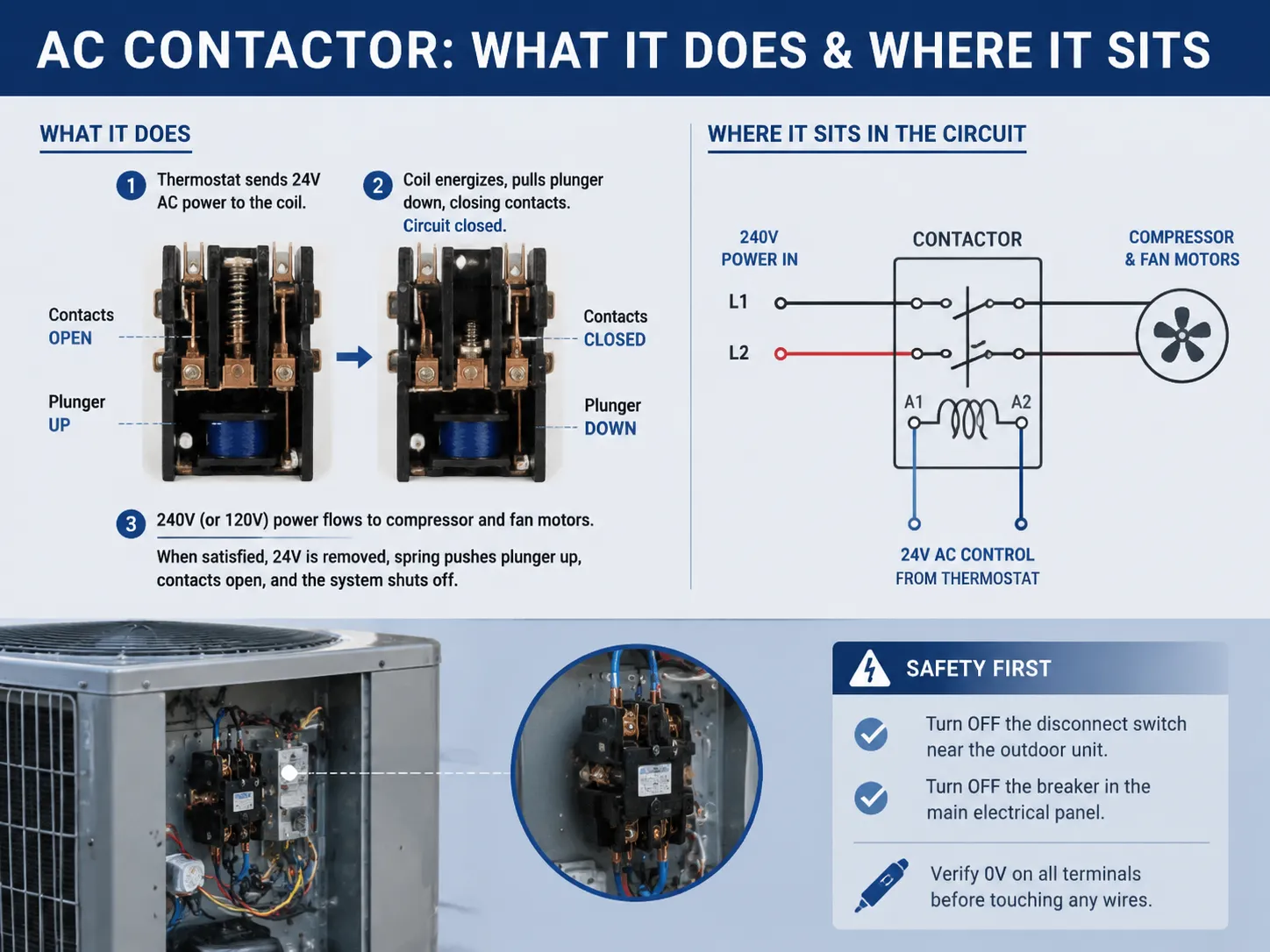
What an AC Contactor Does and Where It Sits in the Circuit
The outdoor condensing unit’s AC contactor is a relay designed to handle the heavy-duty voltage and current of an Air Conditioning (A/C), or Heat Pump (HP) system. When cooling is needed, a thermostat sends 24V AC power to the contactor coil via the thermostat wiring. The energizing of the coil produces a magnetic field that attracts a plunger (downwards) to close the two contacts (to). This ultimately allows the 240V (120V for smaller units) line to be connected to the compressor and fan motors using the contactor contacts. Once the thermostat is satisfied, the 24V is removed from the coil, the magnetic field loses its magnetism, the plunger is again sprung upward by a spring closing both contact sets and shutting off the system.
The electrical access panel of the outdoor unit has a contactor which is primarily a rectangular shape. This may have one, two, or three poles and each pole will have terminals for the Line (incoming power) and Load (Outgoing to compressor and fan) as well as a terminal for the Coil (low-voltage control). First, before you will begin to perform any testing inside of the outdoor unit, you must first locate the disconnect switch which is normally installed on the wall near the outdoor unit and switch that off. You will also switch of the breaker, in the main breaker panel, that provides power to the condenser, you will giving a double-isolation to the contactor; this is a must-do prior to working on the electrical. The contacts on the line side of the contactor will always have voltage present from the breaker to the contactor, regardless of whether the contactor is in the in the closed position or not. Using a non-contact voltage tester, you will isolate the contactor from the voltage by testing each terminal for 0 volts or less, prior to touching any wire connected to the contactor.
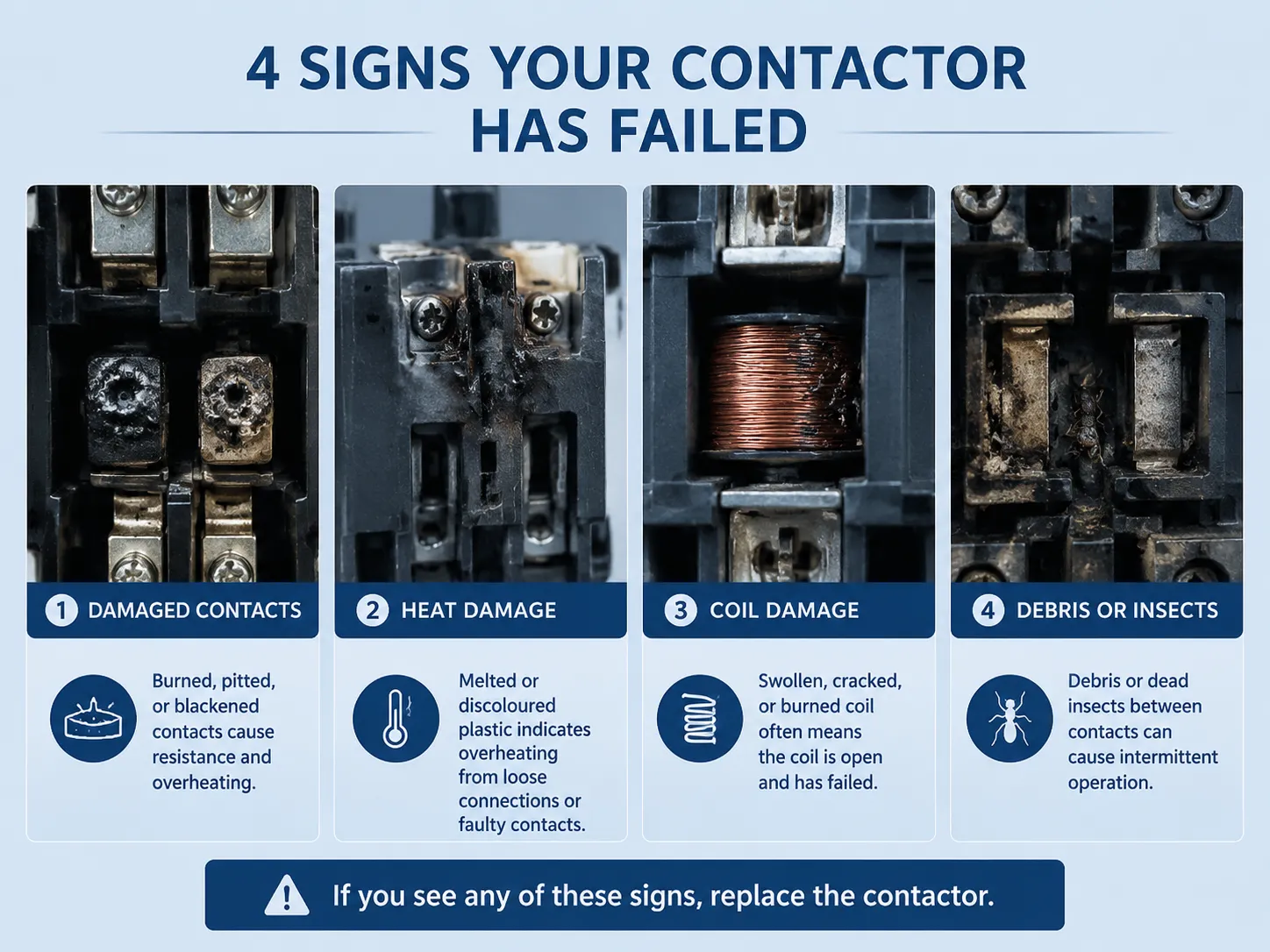
How to Tell If a Contactor Has Already Failed: The Visual Check
Often times a good visual inspection can determine what is wrong before needing to reach for a multimeter. With the power confirmed off and the access panel removed, you can closely inspect the AC contactor:
- Burned, pitted, or blackened contacts. The contact pads should be clean and smooth. If they resemble a cratered, black, or melted lunar surface, then contactor is in a state of failure, even though it may still be functioning intermittently. The pitting of the contacts produces resistance that produces heat, and will soon lead to welding or open-circuit failure.
- Melted or discoloured plastic body. If you see heat damage on the plastic enclosure surrounding your terminal, it indicates that you have either a loose connection or faulty contacts that have repeatedly flashed. Replace the Contactors.
- Swollen or burned coil. In some contactors, the coil winding can be seen from the side. If a coil has been subjected to excessive heat, it will likely display signs like being swollen, having cracks, or showing burn marks. Typically, if a coil has failed, it will show up as an open on a resistance test.
- Debris or dead insects between the contacts. Ants are often attracted to the magnetic field produced by the contactor and will be crushed between the contactor’s contacts when they close. This is surprisingly frequent cause of intermittent operation in warm climates. Cleaning the contact surfaces may occasionally enable the contactors to work again, but if they are pitted due to arcing, they must be replaced.
If there are any signs present when performing a visual inspection of the contactor, then it should be replaced. Testing with a multimeter is still useful for confirming the diagnosis of the contactor as well as determining if there are any upstream or downstream faults; however, once you see the signs in the visual inspection, then you’ve already condemned the contactor.
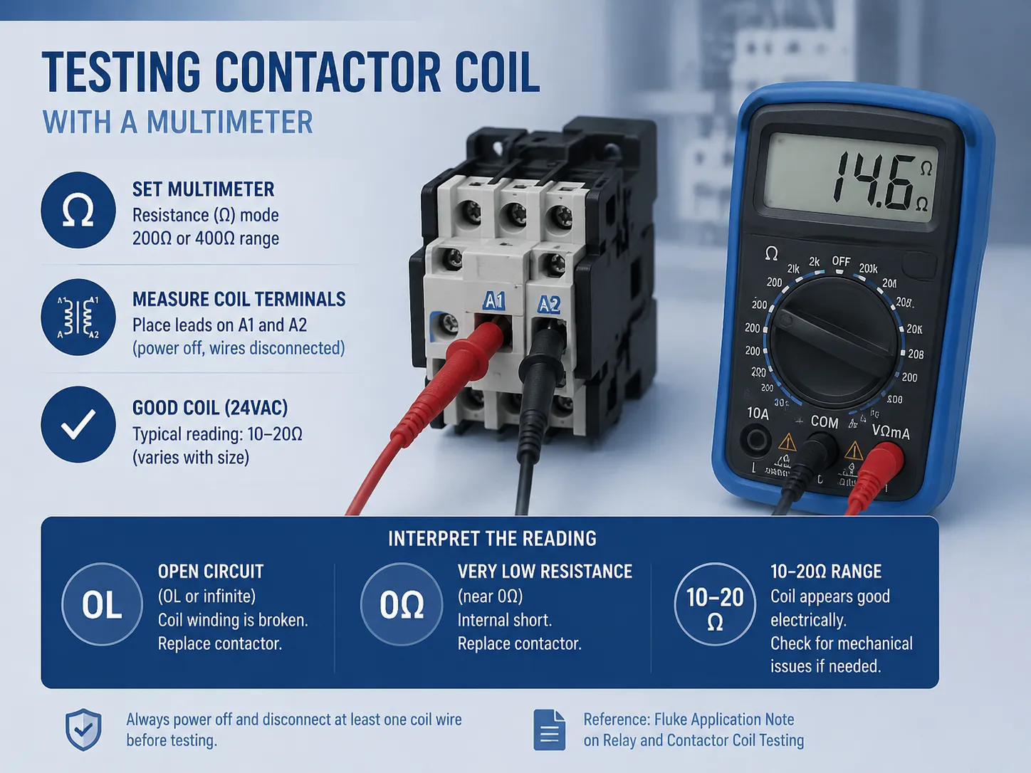
Testing the Contactor Coil with a Multimeter
Once the power is off, testing the contactor can be accomplished on the benchtop or in the field as long as both leads are disconnected. The coil has two terminals, often labelled A1 and A2, and the coil will be 24VAC in almost every home. Set the digital multimeter to resistance (Ω) mode, typically the 200 ohm or 400 ohm mode, and place the leads on the two coil terminals. A 24VAC contactor coil that is in good condition will produce a resistance reading between 10-20Ω. Larger contactors usually produce resistance readings lower than 10Ω and smaller contactors usually produce resistance readings greater than 20Ω. While the actual resistance measurement may not be as important as the reading being selected from one of three categories:
- Open circuit (OL or infinite resistance): The coil winding is broken. The contactor cannot pull in. Replace it.
- Very low resistance (near 0 ohms): An internal short of the coil has occurred. This is rare, but if it happens a shorted coil frequently draws an excessive amount of current and can burn out the thermostat transformer or blow the control fuse. Replace contactor.
- A stable reading in the 10–20 ohm range: Coil appears to function properly electrically. However, there might be some mechanical issues with contactor, i.e. seized plunger, broken spring, etc., but the coil itself is functional.
This resistance test does not require the contactor to be removed from the unit, but the control wires must be disconnected from at least one coil terminal to avoid measuring a parallel path through the thermostat or transformer. A widely referenced application note from Fluke Corporation provides further detail on relay and contactor coil testing.
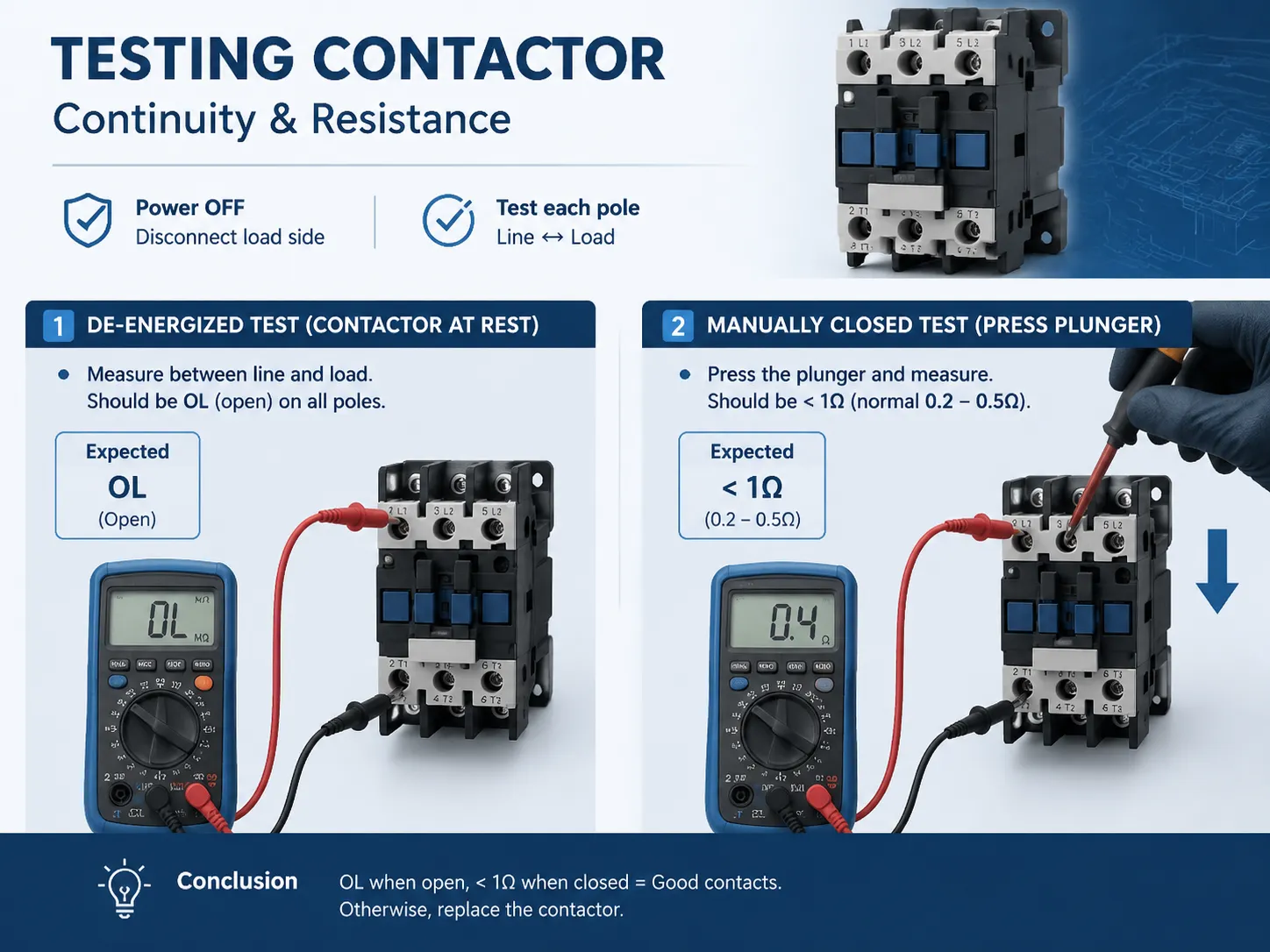
Testing the Contacts for Continuity and Resistance
When the power supply is off and the contactor’s load side terminals are disconnected, test the contactor’s main power contacts to ensure that they show an open circuit with no electrical path when the power is off and that they have low resistance continuity when the contactor is engaged.
To test each pole, you will need to perform the following steps:
- De‑energized test: The resistance of the load terminals of each of the poles should be measured with the contractor at rest between the line terminal and the appropriate load terminal. The resistance measurement should be an OL (open) reading. If any actual resistance is measured when the contractor is in an open position, this indicates welded contacts or carbon tracking across the insulator. The contractor must be replaced.
- Manually closed test: Pressing the contactor’s plunger with an insulated screwdriver will simulate the coil’s electrical action. So long as the plunger remains pressed in, check for ohms between line and load on each pole within the contactor. A good contactor should register less than 1 ohm (normal range 0.2 – 0.5) due to the test lead’s resistance. If the reading is greater than 1 or fluctuates from high to low continuously then this indicates bad contacts therefore you need to replace the contactor.
The manual closure test is both simple and effective in isolating the contacts from the coil circuit and providing definitive evidence of the switch element’s health.
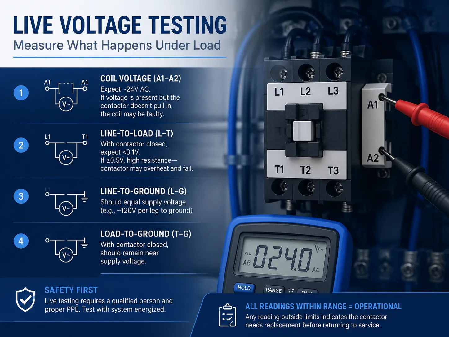
Live Voltage Testing: Measuring What Happens Under Load
Testing and ensuring that the contactor is functioning properly by passing static resistance tests and pulling in under 24 volts requires another form of testing; a live voltage test. A live voltage test can only be accomplished with the system energized, and must be performed with special caution by a qualified person wearing any necessary personal protective equipment (PPE). A resource from Carrier describes safe procedures for measuring the operating voltages of residential split systems.
With the thermostat calling for cooling, measure the following:
- Across the coil terminals (A1 and A2): To get an initial measurement from your test, you will want to verify that you are reading 24 volts AC or thereabouts. If you read voltage but the contactor does not pull in, even though it passed its continuity test, then it should be assumed the contactor’s coil has an internal mechanical failure — potentially due to a stuck plunger.
- Across each line‑to‑load pole: To test a contactor you will need to measure voltage between the line terminal and the corresponding load terminal while running the compressor with the contactor in the closed position. Expect a healthy contactor to measure near zero volts, usually less than 0.1 volt, since the contactors have minimal resistance. If you measure a large voltage drop of 0.5 volts or greater, this indicates that the contactors have a high resistance and are producing heat and the contactor must be replaced.
- Line‑to‑ground and load‑to‑ground at each terminal: The readings show that voltage has been achieved and stability exists. The L-G voltage must equal the supply voltage (normally 120 per leg to ground) prior to the load L-G voltage remaining at or near those levels, when the contactor is in the closed position.
The contactor should be operational electrically regardless of which readings are measured. If any measured reading is outside acceptable limits/replacement is required before returning to service. If any of the readings show a voltage drop across a set of closed contacts, then that is an indication that this particular contactor is experiencing an impending thermal failure.
What If the Contactor Chatters or Buzzes?
If you hear a rapid opening/closing sound (or chattering) from an AC contactor, it may be because insufficient voltage is present at the coil to keep it in the closed position. Low voltage at the coil can be due to: 1) a bad thermostat (the thermostat is either commanding the unit to shut off or keep the compressor running), 2) bad or loose connection(s) between the thermostat and 24v control wiring, or 3) an undersized or defective transformer, which reduces line voltage down to 24 volts (transformers are typically mounted in the outside, high-voltage section of an air conditioning system). To check whether there is enough voltage at the contactor coil terminals, you will have to measure it while the contactor is chattering. The voltage at the coil terminals should read no lower than 20 volts AC; if it does, the issue exists upstream from the contactor. If you have a measurement of a steady 24 volts AC at the contactor’s coil terminals, but the contactor continues to chatter, the coil (or the shading ring) is defective.
A defective shading ring will create a loud buzzing noise when it is energized and not allow the plunger to hold firmly. You will need to replace the contactor to correct the problem.
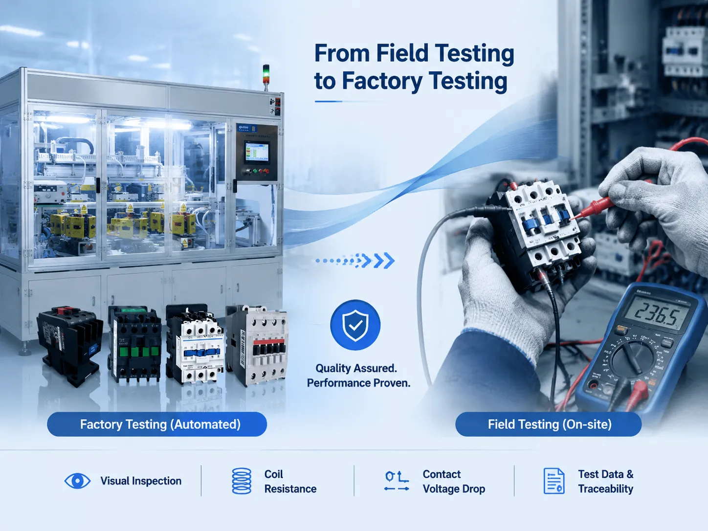
From Field Testing to Factory Testing: The Full Spectrum of Contactor Verification
As part of a 30-minute service call, technicians perform many tests, including performing a visual inspection, assessing the coil’s resistance, and checking the drop in voltage (head of contact) across the contact points. The amount of time spent conducting these activities represents a small sampling of quality assessments performed on each contactor prior to leaving the manufacturing line.
To achieve this level of quality in the manufacturing process, manufacturers rely on various quality assurance processes — including automated testing. AC contactor testing can be performed with a single machine’s coordination of all automated test processes in one integrated station. Following the automated test processes described above, the manufacturer generates the test data needed for the technician to provide assurance to their customer that the contactor was manufactured to meet its nameplate specifications.
For manufacturers of contactors, relays, and similar electromechanical devices, automated test equipment provides the throughput and the documentation that manual testing cannot achieve. Benlong Automation’s umfassendes Prüfgerät für Wechselstromschütze is an example of such a system: it integrates the electrical and mechanical tests required for production‑line quality control into one station, delivering calibrated, repeatable results with digital traceability. This is the upstream counterpart to the field tests described in this guide — the same parameters, measured with the same physics, but at production speed and with full documentation. A contactor that has been individually tested at the factory arrives in a technician’s hands with a known performance baseline, making the field test a confirmation rather than a discovery.
Häufig gestellte Fragen
How do I tell if my AC contactor is bad?
If you are able, check visual indicators of bad contacts; burnt/pits on the contacts, melted plastic on the body of the contactor, or the coil is swollen. An Electrical bad contactor will show as an open coil (no continuity), welded contacts (will have continuity when de‑energized) or an excessive voltage drop across closed contacts (greater than 0.5V). A buzzing or chattering contactor is also failing.
Can you test a contactor with a multimeter?
Using a digital multimeter, you can conduct full testing of an AC contactor. First, measure the coil resistance from A1 to A2 (10-20 ohms on a 24V coil). Second, measure the contact resistance from line to load while manually closing the contactor (less than 1 ohm). Finally, with power on, measure continuity through both contacts (very low voltage drop).
What should an AC contactor ohm out at?
Depending on how many contacts are in the contactor, if you measure the resistance through the coil of a typical 24- volt AC contactor, it should be between 10 and 20 ohms. A simple single-pole contactor will be closer to 10 ohms, while a larger three-pole would be closer to 20 ohms. If you have an open-circuit (OL) or very close to zero readings, the coil has failed.
How to check HVAC contactor with multimeter?
Deactivate the electricity to the outdoor unit at the circuit breaker. Check for zero volts between the pin terminals on the outdoor unit. Disconnect the coil wires from the following terminals. Use a multi-meter to determine the resistance of each coil terminal; anticipate 10 to 20 ohms of resistance. Push the stem of the plunger down to measure the line-to-load resistance at each pole: anticipate less than 1 ohm of resistance. When the contactor is not energized (disconnected from the line), the line-to-load should be an open circuit. If the contactor passes these tests, reconnect the electricity to the outdoor unit at the circuit breaker and test to see if the coil voltage is 24 v ac and check for near zero voltage drop across each of the closed contact points.
References
- Fluke Corporation — How to Test a Relay — Application note on coil and contact testing with a digital multimeter.
- Carrier — Residential Air Conditioner Service Guides — Manufacturer service documentation for split‑system AC units.
- Trane — HVAC Service and Troubleshooting Resources — Diagnostic procedures for residential and light commercial HVAC equipment.
- ACHR News — The Air Conditioning, Heating, and Refrigeration News — Trade publication with technical articles on HVAC component diagnosis and replacement.
Testing an AC contactor is a sequence of logical steps: visual inspection, coil resistance, contact continuity, and live voltage drop. Each step confirms or rules out a specific failure mode. A contactor that looks burned, reads open on the coil, or shows a voltage drop across closed contacts is a contactor that has reached the end of its service life — and replacement is a straightforward, inexpensive repair that restores the system to reliable operation. Whether the test is performed on a hot rooftop with a handheld multimeter or on a factory floor with an automated test machine, the parameters are the same because the physics is the same. Mastering that sequence turns an intermittent cooling complaint into a definitive diagnosis, every time.