benlong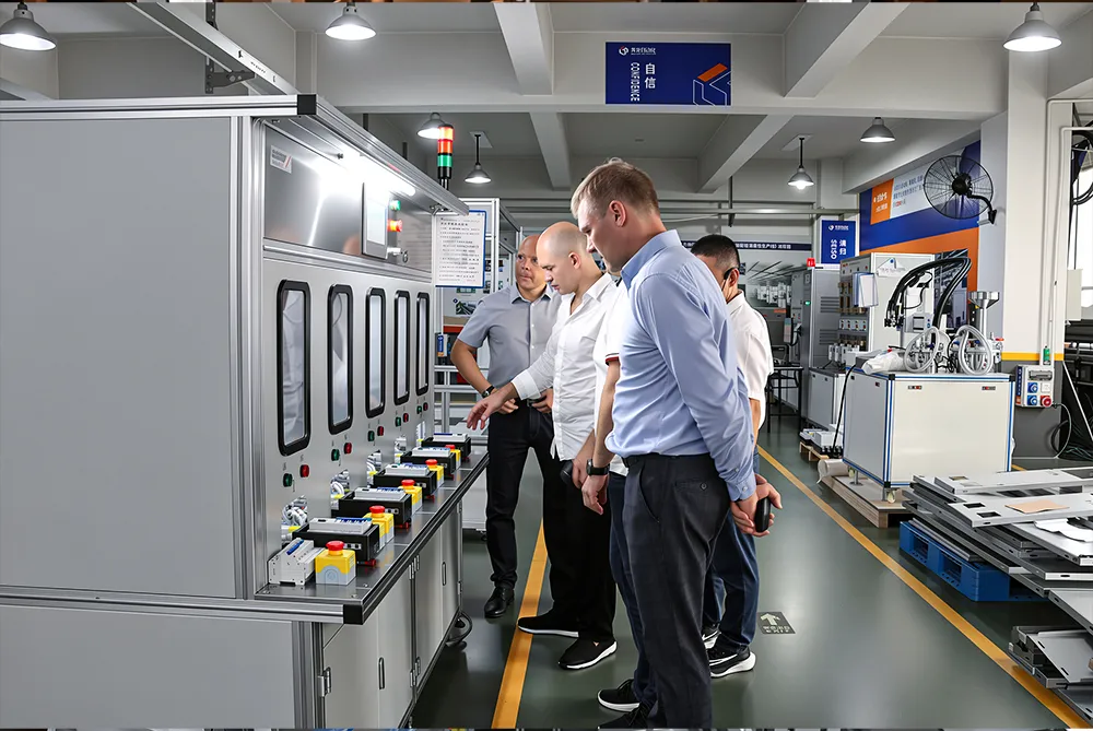


What Is Thermal Calibration and Why Do MCB and MCCB Makers Need It?
In a circuit-breaker factory, the moment that decides whether a finished MCB is safe or scrap is thermal calibration. It is the step where the bimetallic element inside each breaker is trimmed and verified so that the device trips within the exact time window demanded by the standard — not a second too early, not a second too late. Buyers often call this stage the delay test, because what is really being measured is how long a breaker takes to trip at a given overcurrent. For manufacturers of MCBs, MCCBs, and RCBOs shipping into markets that require IEC compliance, getting this stage right is the difference between a product that protects a circuit and one that fails an audit. This article explains what MCB thermal calibration actually is, how the delay test splits into long-time and short-time verification, why the B, C, and D curves have different pass criteria under IEC 60898-1, and what equipment runs the process on a modern production line.
By Huang Xiaolei | Benlong Automation
What Is Thermal Calibration in Circuit-Breaker Manufacturing?
The thermal-magnetic tripping technique is employed by nearly all low-voltage circuit breakers. An overload situation is addressed using a bimetallic strip, which consists of two metals placed together with differing rates of thermal expansion. So when the current exceeds specified limits, the strip becomes hot, bending towards the metal that expands at a slower pace. A proper amount of bending will cause the strip to let go of the trip latch. After an overload, the higher the current, the faster the heater, and therefore, the quicker the trip will occur. This feature of the device proves that thermal calibration is the whole process of manufacturing of circuit breakers involving adjustment of the bimetal strip, which will be either bent, in which case the screw will be adjusted or the trip linkage will be moved to ensure the trip time falls within the range predetermined by the current standard for every test current.
Its significance cannot be overestimated, as it will allow sorting out the terms easily confused. Calibration means adjusting the mechanism to hit the targeted window of space or to verify that it gets to that spot. In reality, the two processes occur simultaneously, as the operator injects current and measures time before adjusting the strip for unit re-checking since an important fact to remember is that mechanical and materials properties differ for each bimetal, leading to the necessity of individual calibration in the first place. A faulty device that doesn’t meet the calibration requirements may trip during a normal mode of operation or, even worse, get stuck during an overload operation.
Thus, two characteristics are considered in the process — the accuracy and the repeatability of the output. An important detail is that if there are any problems with the equipment, the operators will be able to check the trip from the cold start. The range of adjustments is rather strict, usually several percents at the trip current, which means that the range of errors for the bench should be much smaller than the one for the calibration device. This explains the need for the reliable calibration equipment to ensure the efficient operation of the device.
The Two Trip Functions Behind Every Delay Test
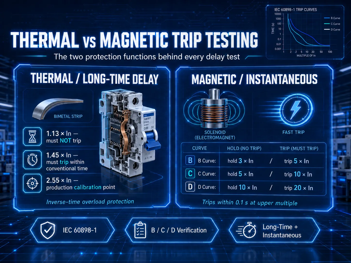
In order to understand why the delay test is divided into two segments, we have to understand that there are two independent protective features in the breaker. The thermal protection, or overload protection, comes from the bimetal strip, that reacts leisurely, from seconds to hours, therefore forming the long time portion in the trip curve. This is the one that is set by the thermal characteristic. The magnetic protection or short circuit protection comes from the electromagnet or solenoid, that responds with a speed of milliseconds to the high fault current, thus forming the short time or instantaneous portion of the curve.
If we look at the log-log time-current graph published by every producer, we see that the thermal area corresponds to the upper sloped part of the curve while the magnetic area corresponds to the near-vertical lower part. In manufacturing practice, these two characteristics are tested with different currents, timing tolerances and sometimes different test benches. This is where the long-delay versus short-delay splitting comes from: long-delay characteristic tests the thermal bimetal, and short-delay or instantaneous one tests the magnetic coil. So, it is extremely important to keep these two types separate.
Long-Time-Delay Testing: The Core of Thermal Calibration
The long-time-delay test is the heart of circuit breaker thermal calibration. It affirms the bimetal activation at proper time under designated overload electric currents. In accordance with IEC 60898-1 standard, all tests must be conducted in conditions of air temperature of +30 °C and from the cold starting point; current characteristics are shown for the three point of overload, which remain the same for all B, C and D curves.
| Test current | Requirement | Conventional time |
|---|---|---|
| 1.13 × In (conventional non-tripping current) | Must NOT trip within the conventional time | ≥ 1 h (In ≤ 63 A); ≥ 2 h (In > 63 A) |
| 1.45 × In (conventional tripping current) | Must trip within the conventional time | < 1 h (In ≤ 63 A); < 2 h (In > 63 A) |
| 2.55 × In | Must trip within the stated band | 1 s to 60 s (In ≤ 32 A); 1 s to 120 s (In > 32 A) |
The pair 1.13 × and 1.45 × establishes the limits of acceptable overload performance of the circuit breaker; while the circuit breaker has to endure slightly over 13% overload without false tripping, it needs to be able to disconnect even a 45% overload in a conventional manner. These factors define the location of the heat curve on the graph. . The only reason that the traditional time changes from one hour to two hours after 63 A is that larger circuit breakers that have larger contacts have much bigger heat capacity and take longer time to become stable.
With regard to production, the point 2.55 × In is practically used to calibrate the circuit breaker as it allows to measure the time of disconnection in seconds as opposed to the hour gained in terms of traditional measurements. Thus, a specific amount of current can be passed through the circuit breaker while measuring the time of trip time in order to adjust this time using the servo or the operator. The more time-consuming measurements performed by means of the use of points 1.13 × and 1.45 × support the results obtained above.
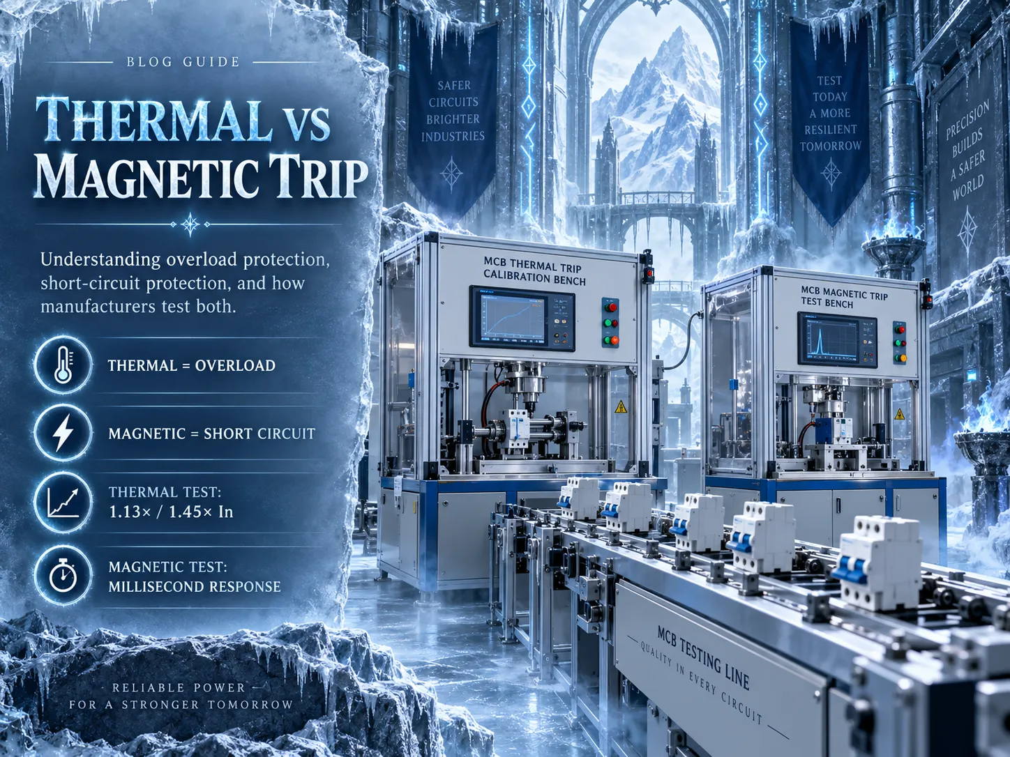
Benlong builds equipment for exactly this stage. The MCB long time thermal calibration bench runs overload testing to IEC 60898-1 across multiple stations with a high-stability current source, while the semi-automatic thermal trip calibration bench Type-A and its card-based sibling Type-B handle programmable overload calibration with fast changeover between MCB families. For MCCBs governed by IEC 60947-2, the reference points shift — conventional non-tripping current becomes 1.05 × In and conventional tripping current 1.3 × In — but the calibration principle is unchanged.
Short-Time-Delay and Instantaneous Testing: Where B, C, and D Differ
The second portion of the delay test assesses the magnetic element or short-circuit response. This is what customers frequently refer to as either short time delay or time delay test and where the B, C, and D curves begin to behave differently. The level at which the magnetic trip occurs is defined by the amount of rated current needed to trip the breaker as per the instantaneous convention of 0.1 second. A lower multiple corresponding to the curve type indicates the current at which the breaker is still required to keep in service, and an upper multiple implies where the breaker must trip.
| Curve type | Must NOT trip within 0.1 s at | Must trip within 0.1 s at | Typical application |
|---|---|---|---|
| Type B | 3 × In | 5 × In | Resistive loads, long cable runs, lighting |
| Type C | 5 × In | 10 × In | General sockets, small motors, mixed loads |
| Type D | 10 × In | 20 × In | High-inrush loads: transformers, large motors |
The test is run in two phases per curve type. First a hold test confirms the breaker does not trip within 0.1 s at the lower multiple — 3 × In for B, 5 × In for C, 10 × In for D. Then a trip test confirms it does trip within 0.1 s at the upper multiple — 5, 10, and 20 × In respectively. Take a Type C 16 A breaker: it must ride through 80 A (5 ×) without an instantaneous trip, yet must snap open almost immediately at 160 A (10 ×). The same 16 A breaker in Type B would trip instantly by 80 A, and in Type D would tolerate up to 320 A before the magnet acts. This spread is exactly why curve selection governs inrush tolerance and downstream coordination: a D-curve rides through the momentary surge of a motor or transformer that would nuisance-trip a B-curve.
One point deserves emphasis for anyone writing a test specification. The pass criteria that change between B, C, and D belong to the magnetic (instantaneous) trip, not to the thermal overload trip. The bimetal side, the true thermal calibration, is the same for all three curves. And in an MCB this short-circuit response is instantaneous rather than genuinely delayed; the phrase short-time delay is used loosely on the shop floor. A real, intentional short-time delay band only appears in MCCBs with adjustable trip units, covered next. For the MCB and small-frame MCCB magnetic check, Benlong’s MCCB manual magnetic trip test bench is purpose-built, with a programmable 5–10 × In current source and millisecond-level timing for a clear pass/fail judgement.
Which Standard Applies: IEC 60898-1, 60947-2, and 61009
The appropriate passing criteria depend on the standard to which the product is certified, and the wrong application poses a real danger in terms of risks. MCBs applied in domestic uses and similar environments apply the IEC 60898-1 standard, which specifies the B, C, D classifications. IEC 60947-2 standard governs the use of MCCBs and industrial circuit breakers, so it has its conventional currents (1.05 × and 1.3 × In) and more flexible features. IEC 61009-1 standard governs the use of RCBOs, or residual current circuit breakers which, in addition to being exposed to residual current tests, must also undergo the same tests as MCBs for thermal and magnetic operations. A single switch may be certified according to both standards, yet the temperature reference may be arranged differently, depending on the standards used.
The reference temperature is one of the factors. According to IEC 60898-1, the calibration is performed at 30 °C, while devices compliant with IEC 60947-2 undergo testing at 40 °C. At the same time, a self-same device can be tested using other temperature levels for each of the mentioned standards. The reference temperature will also influence the derating table used by consumers, so if the breaker was tested using the wrong reference, it may fail after passing standard tests. Thus, fixing the temperature during testing is not only a laboratory formality but also a definite quality requirement.
MCCB Thermal Calibration and the LSI(G) Delay Bands
Molded-case circuit breakers add a layer of complexity. Smaller thermal-magnetic MCCBs are calibrated much like MCBs, by trimming a bimetal for the overload band and verifying the solenoid for the short-circuit trip. But many modern MCCBs use electronic trip units, and here MCCB thermal calibration becomes a matter of setting and verifying programmable protection parameters rather than bending metal. These trip units are usually described with the LSI or LSIG scheme, and each letter is a separately adjustable protection band:
- L, long-time delay: the overload function, equivalent to the thermal element, with adjustable pickup current and time delay that define the inverse-time overload behavior.
- S, short-time delay: a genuine, intentional delay on moderate fault currents, used so that a downstream breaker can clear a fault first and preserve selectivity. This is the true short-time-delay band that MCBs simply do not have.
- I, instantaneous: immediate tripping above a high threshold with no intentional delay, for severe short circuits.
- G, ground fault: optional earth-fault protection on four-pole and higher-specification units.
For an electronic MCCB, the delay test verifies that each band trips within tolerance at its programmed settings, injecting current at the L, S, and I thresholds in turn and timing the response. For a thermal-magnetic MCCB, it verifies the bimetal and solenoid directly, exactly as for an MCB but at higher currents and larger frames. Either way the equipment must source much higher test currents than an MCB bench. Benlong’s MCCB Laboratory Integrated Testing bench is designed to run magnetic trip testing, thermal calibration, and long-duration thermal calibration in one station, which suits both the R&D lab and the type-test room.
How Thermal Calibration Is Done on a Production Line
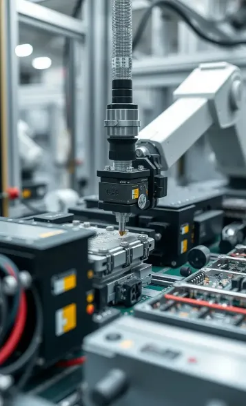
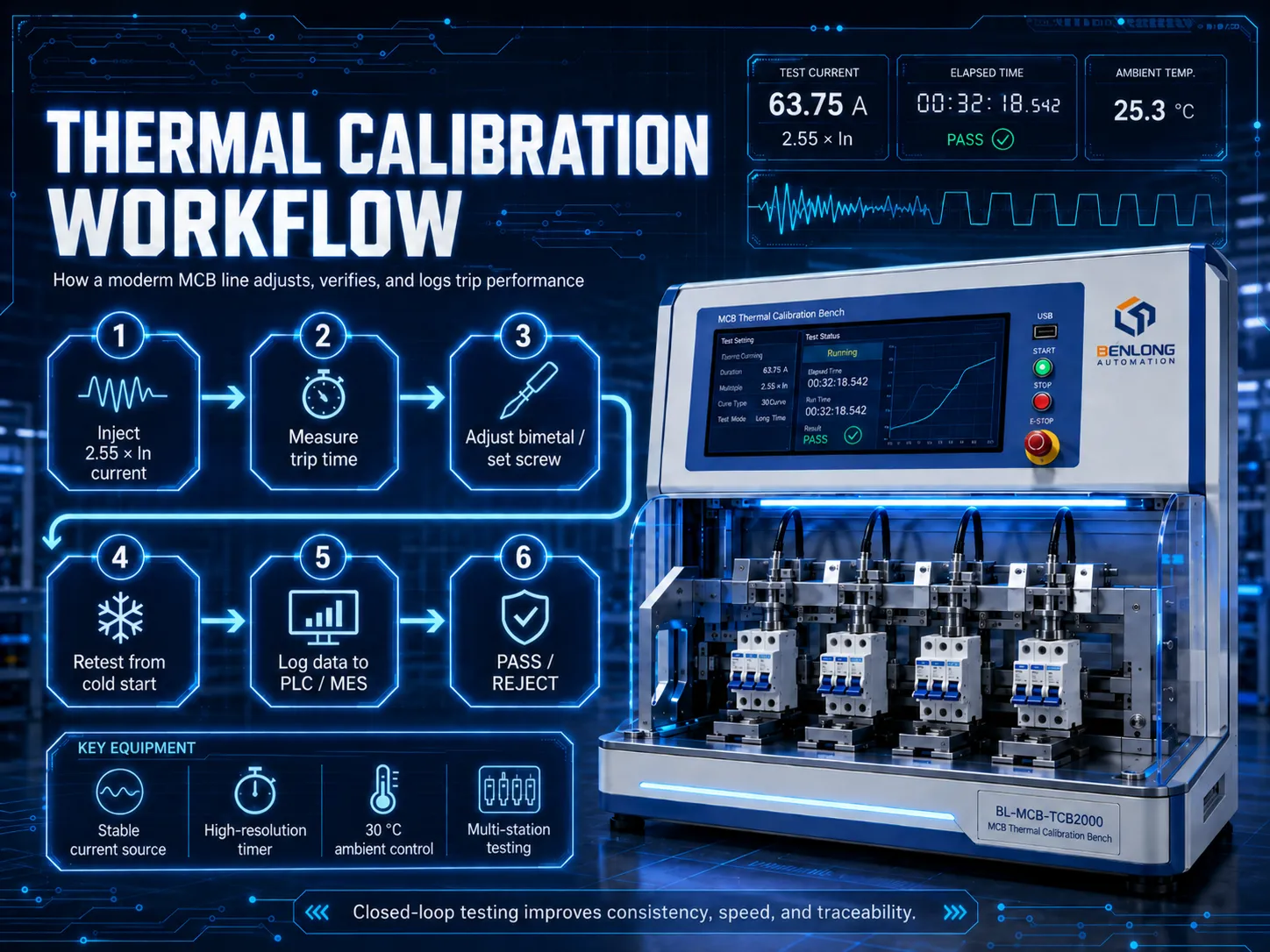
A typical thermal trip calibration workflow on a modern MCB line runs through a repeatable sequence. A controlled overload current, commonly at 2.55 × In, is applied through the breaker under test using a stabilized source with low harmonic distortion, since a distorted waveform changes the heating and skews the reading. A high-resolution timer records the exact instant the breaker opens, typically to a fraction of a percent of the reading. If the trip time falls outside the window, the bimetal is bent or its set-screw adjusted — by an operator on a semi-automatic bench, or by a servo head on a fully automated cell. The unit is then re-tested from cold, and the pass/fail result and trip time are logged, often exported by USB or pushed to an MES for full traceability. Throughout, because the standard references 30 °C, the test-area temperature is monitored and compensated; calibrating at the wrong ambient temperature is one of the most common causes of field trip-time errors.
Automating this sequence pays off in three ways: consistency, because a servo adjusts more repeatably than a hand; speed, because parallel stations absorb the long conventional tests; and traceability, because every unit’s data is captured rather than spot-checked. Higher-specification products are often calibrated on 100% of units, while commodity MCBs may follow a defined sampling plan. Quality upstream matters too — the bimetal assembly has to be built consistently before it can be calibrated at all, which is why Benlong also supplies the MCB thermal trip set automatic welding line for producing the thermal trip subassembly with repeatable weld quality. Consistent components entering calibration mean fewer units drifting outside the window and less rework downstream.
The current source itself is the quiet hero of the whole stage. Because the bimetal responds to heating, the trip time depends on the true RMS current and its waveform quality, not just a nominal set-point. A source that sags under load, drifts as its own components warm, or carries significant harmonic distortion will heat the strip differently from the clean sine wave the standard assumes, and every unit calibrated against it inherits that error. That is why a stable, closed-loop current source with low total harmonic distortion, combined with solid, low-resistance test contacts, does more for yield than almost any other single factor on the bench.
Why Breakers Fail Delay-Test QA
Even if it is designed well a breaker still may produce rejects if its manufacturing process has drifted. Most common reasons for a breaker not passing its delay test include high ambient temperature deviating from the reference temperature of 30 °C, which shifts the overall thermal band left or right; unstable current, which alters the amount of heat supplied to the bimetal; improper resistance at the terminals, which creates additional heat; insufficient settling time between tests, so that the bimetal can retain residual heating; wrong curve card or program applied; and mechanical drift after calibration, which causes high scatter between successive tests. Most of these issues arise due to control problems and can be eliminated if the production bench has stable current supply, excellent temperature compensation, and an automatic data recording system.
Delay testing is only one pillar of breaker quality control. It sits alongside dielectric and insulation verification — if you are building out a full test plan, our explainer on hi-pot testing covers the withstand-voltage side that runs in parallel with the thermal and magnetic checks.
Choosing Thermal Calibration and Delay-Test Equipment
Matching the bench to the product matters. A single MCB family at modest volume is well served by a semi-automatic calibration bench; a plant running many models benefits from card-based changeover so a line can switch families in minutes; and an MCCB or ACB shop needs higher-current, larger-frame benches with the range to reach the required multiples. Benlong’s full range of these systems sits under the Test Bench Project catalog, which spans MCB thermal calibration benches, MCCB magnetic trip benches, integrated laboratory testers, and comprehensive ACB test stations. Because every plant’s model mix, target throughput, and cycle time differ, these benches are typically configured to the customer’s product rather than sold as fixed catalog units.
Conclusion
Thermal calibration is where a circuit breaker earns its rating. The delay test that verifies it divides cleanly into a long-time-delay part, which sets and checks the thermal bimetal against the IEC 60898-1 overload points, and a short-time or instantaneous part, which checks the magnetic trip — and it is the magnetic side that gives the B, C, and D curves their different pass criteria. Get the ambient, the current waveform, and the timing right, calibrate each bimetal individually, log the results, and the outcome is a breaker that trips exactly when it should and holds when it should. For manufacturers scaling that process, the right combination of calibration and delay-test benches turns a slow, operator-dependent task into a repeatable, traceable production stage.