benlong


How to test Solid State Relay
Mastering proper testing methods for solid state relay devices is a valuable skill for people engaged in the creation, management, and procurement of electrical control systems. Because solid state relays do not contain mechanical parts, they can fail differently from traditional electromechanical relays and cannot be analyzed using standard testing procedures. Quite often, SSRs fail quietly, which may result in false triggering of equipment or even the current leaking while the system should be switched off completely. The techniques discussed in this article provide guidance for various types of SSR testing, beginning from a simple meter check and concluding with a full electrical verification testing used on the production floor.
Why Testing an SSR Is Different From a Mechanical Relay
A mechanical relay is able to open and close metallic contacts so that when using a meter set in continuity the readings obtained are very clear: closed means almost zero ohms, open means infinite. An SSR on the other hand does its switching using solid state devices like TRIAC, SCR or FET and that is a totally different game altogether. Even when not active a good SSR permits a small amount of leakage current to flow when it is off, and in the active mode it drops a certain voltage instead of acting like a perfect closed switch. Because of this a resistance measurement made across the output terminals of a normal SSR can be rather confusing and might indicate a faulty part. One of the main reasons that makes solid state relay testing complicated is that people just rely on the same principles that they would apply to mechanical relay.
Necessary Preparation and Equipment
Before beginning any work, collect a digital multimeter, which will possess a diode and resistance measuring function, as well as a low-voltage direct/alternating current supply appropriately matched to the relay control specifications. It is also recommended to use a small test load, for example, an incandescent lamp or any tubular heating device suitable for position. A high voltage tester is required for the purpose of safety and isolation checking if the manufacturer recommends verifying the separation between the input and output circuits. The manufacturer’s specification gives information on part number, control voltage, output current, and the leakage current in the off-state. It is crucial to know if it is a DC or AC circuit in order to predict the future behavior of the device. Zero-crossing SSR is able to switch on only when the voltage is equal to zero; for this reason, it is applied for resistive loads, while the random-fire model is used for phase control.
Be Aware of Safety Risks
The output of the solid-state relay could be connected to the mains voltage, and its metal base is likely to be very close to live semiconductor junctions. Therefore, the circuit should be de-energized, all capacitors should be discharged, and the voltage should be checked with the help of a digital multimeter before the operator enters the circuit. During the powered operational test, a properly fused circuit must be used in order to connect the relay and one hand should be kept behind one’s back while working near live wires. In case of isolation testing, one should keep in mind that high voltage tester uses several high volts and must be operated by the trained employee only when the device is taken away from the rest of the machine.
How to Test a Solid State Relay With a Multimeter
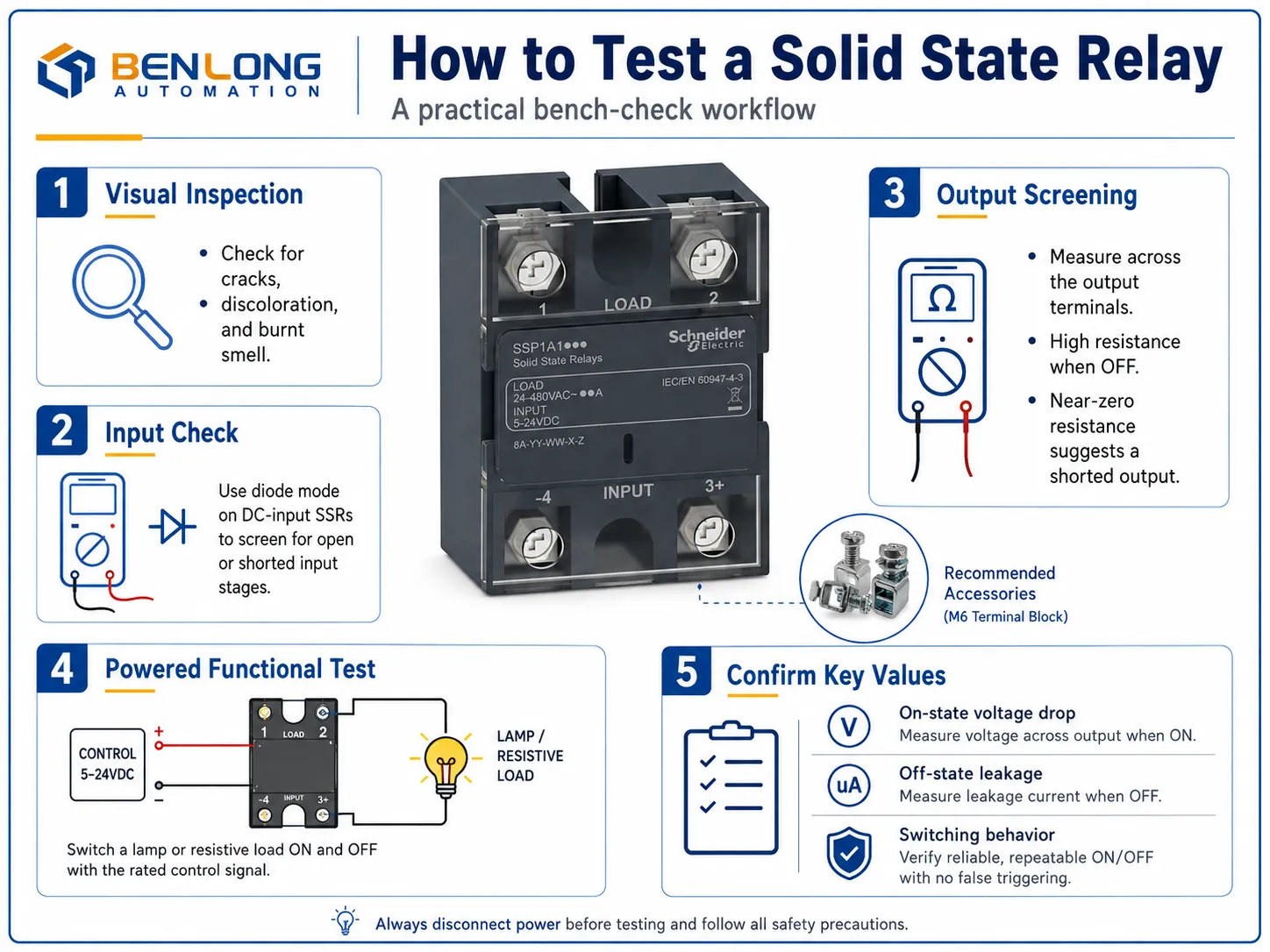
The frequent question that people ask in workshops is how to test the solid state relay, and the truth is, while the meter can catch gross failures, it cannot tell the status of the device completely. But just by performing the meter check, you can screen most of the defective and shorted solid-state relays in just a couple of minutes. First of all, make sure that the device is disconnected from the supply. Then switch the meter to diode mode and check the input or control terminals of the solid-state relay. If this solid-state relay works on DC input and uses opto couplers and LED, you might get a forward voltage in one direction and an open reading in the opposite direction, just like a diode. If the open reading is obtained in both directions, then it suggests that the input is open. On the contrary, if the readings are very close to zero in both directions, that points to a short in the input.
The next step is to check the output terminals. Set the meter to resistance and check the output. In working SSR you should see a high resistance in both directions, which means that the semiconductor is not conducting. If the readings are close to zero in one direction, that indicates that the output is shorted, which is the most commonly faced and the most dangerous failure of SSR.
The Power-Driven Functional Experiment
The fully optimized bench test is termed the power-driven functional experiment in which the functioning of the device is confirmed. Connect the output terminals in series with the lamp under test and the relevant supply while maintaining the control connection free. In absence of the control voltage, the lamp must remain dark. If the lamp glows mildly, it indicates the shortage in the output. Now supply the input with the control voltage and the healthy relay will turn on the lamp with full brightness. After cutting off the control voltage, the lamp must become entirely dark. If the output does not turn on with the control voltage on the input, it indicates that the device is open or if it does not turn off while the control voltage is off, it means that the output semiconductor has failed.
While the device is still powered on, it is possible to measure the voltage drop at the time of work using the voltmeter. The voltage drop of roughly 1-1.5 volts on AC SSR TRIAC is considered normal and if it is excessively high, it implies that the semiconductor is aging and getting hot. Measuring the leakage of the switched off state through the voltmeter will show how well it is switching. So these two readings are what distinguishes the poor device from the good one.
Testing the SSR for AC Input
Not all units take the signal with DC control. In case of AC-in unit, the control voltage is expected to be ranging from 90-280 AC, so the previously mentioned formula of the diode check does not work in this case. For this type of devices, the safe and easy way would be to perform only the powered functional test: turn on the specified control AC voltage and check whether the device was switched on with it or not. Thus it is not possible to measure the resistance in an AC unit due to the low voltage and therefore it is hard to interpret the results obtained through the use of measuring instruments.
Isolation and Hi-Pot Testing
A multimeter cannot check some properties like the condition of the insulation between input and output circuits. While this barrier ensures that high voltage does not reach the low-voltage control side of the system, it is an important safety specification that needs to be checked through a dielectric withstand or hi-pot test that consists of applying high voltage to the input/output circuit for some time while monitoring the possibility of a breakdown or excessive leakage current. A device that passes the functional test but fails isolation testing solid state relay procedures is unsafe and must be rejected, because the invisible insulation fault will not show up in any switching check. This is why serious quality programmes treat hi-pot verification as mandatory rather than optional.
Thermal Behavior and Thermal Faults
When an SSR is activated, it has the propensity to drop in voltage and cause heat, which accounts for the majority of failures in the field. An SSR that functions normally in the laboratory might begin to act strangely after conducting a current for a few minutes in a low grade heat sink. In case there is any suspicion of thermal failure, it is recommended to perform the powered functional test with the rated load over an extended period of time and to monitor the baseplate temperature. If a device shows an increase in the on-state voltage drop and erratic switching behavior, it means that its semiconductor is functioning beyond its limits. Proper heat sinking and thermal interface material are parts of the solution, though thermal cycling during the testing period brings the problem to light. As a result, SSRs that are sized generously with sufficient current margin and are mounted on an adequately rated heat sink will pass tests well, while one that is unbearably cured will fail the test within a few minutes. Recording the baseplate temperature at the end of the experiment provides a standard for future comparisons.

How Can One Test a Solid State Relay
Bringing together some of the various checks makes it easy to identify a fail unit. One of the main signboards of a failure is the load that remains energized regardless of the control signal. The opposite problem is related to the open output as well as dead input stage. When the load flickers and switches poorly and only turns on when it gets warm, it proves the presence of poor quality semiconductor or an issue with the control. In general, to be able to find out whether a solid state relay is bad, the readings of the meter and functional switch test along with the isolation check should be used together.
Testing In-Circuit Versus Out-of-Circuit
The significance of performing the check is equal to the importance of the location of check. The cleanest check is when we test the relay removed from the machine. This is the best way, as nothing can affect your readings. Of course, meter only measures the relay, functional testing only requires load known to you, and there are no parallel circuits complicating your measurements in this case. However, if the question is of ultimate importance, it is better to remove the SSR and test it. Testing in circuit is an easier and faster way as the device is wired, but many elements, control circuits, and the load may affect the result; thus, the data received from in circuit testing may be regarded only as preliminary information. If it is suspicious; check it out of the circuit: otherwise, you may conclude wrongly about the faulty element and replace working device to have the real problem left unresolved.
Common Mistakes to Avoid
There are some common mistakes made by the professionals as well. The first mistake is to expect that the terminal of an SSR will show an open circuit or short when measured with a ohm meter; semiconductors behave differently and the usual leakage values are confused with failure readings. The second mistake is to apply the incorrect control voltage during the testing process either by supplying insufficient voltage that does not work the control circuit or wrong voltage type (e.g. supplying DC instead of AC). The third mistake is to conduct the test without the load that may hide the defecting output since there is no current flowing through the system. The fourth mistake is not performing an isolation test, and making the assumption that a device switching properly must be safe. There may be perfect switching of a relay but it may losing the insulation barrier at the same time.
From Bench Testing to Production-Scale Testing
The preceding discussion revolves around the idea of testing each relay separately, which is fine in terms of its application in maintenance and repair work, but the task of producing is a different story altogether. During the operation of a facility that manufactures hundreds and thousands of SSRs per shift, testing every single SSR produced manually is simply impractical, slow and impossible to document appropriately for certification needs. The individual processes do not differ much from the ones described in the previous sections; however, they need to be automated, arranged in a sequence, and documented. The tested characteristics include rated current capacity, output voltage drop, input control current, insulation resistance, and if necessary, thermal cycling. This is the point where how to test solid state relay knowledge scales from a workshop skill into a production discipline.
Benlong Automation builds exactly this kind of integrated line. The Solid State Relay Automated Production Line combines SMT placement, soldering, dispensing, and a full functional test suite that measures rated current, output voltage drop, isolation strength by hi-pot up to two thousand five hundred volts AC, and thermal characteristics, then uploads every result to an MES system for complete per-unit traceability. Because the same electrical checks you perform manually are executed by programmable testers at a rate of well over a thousand units per shift and logged automatically, a manufacturer gains both consistency and the audit trail required for IEC 62314 compliance. For anyone moving from occasional bench testing to standardised, certifiable output, an automated line turns a manual routine into a repeatable, documented process.
Building a Simple Testing Routine
A good routine connects the techniques into a system which can be applied each time. Start from visually checking for any breaks, discoloration and burning smell, since any physically damaged equipment fails before it can be tested. Next go to the reading screen of the meter on the input and output to identify any dead or short devices. Proceed with the live test to ensure proper on-off functioning of the device under a normal load and measure the voltage drops during operation. Conclude with the isolation test in any case of safety or certification. Working in this order means each step either clears the device or stops you before you waste effort on a part that has already revealed a fault, which is the practical essence of good SSR testing.
Conclusion
Understanding how to test solid state relay devices is about respecting what makes them different from mechanical relays and using the right tool for each layer of the check. A multimeter checks for major input and output problems, a powered functional test confirms smooth switching under load while measuring on-state voltage drop and leakage, and a hi-pot test ensures the isolation barrier which cannot be identified by any multimeter. These tests are sufficient for maintenance and troubleshooting. In case of large-scale manufacturing, the same principles are automatically and traceably applied on a single production line, which guarantees that all products delivered will be proved and documented. Learn how to understand the singular checks and then you will know how to work with any SSR.