benlong



How to Test Continuity with a Multimeter
Every electrician, technician, and DIYer bears the burden of the same dilemma: is this wire connected properly? Is this fuse blown? Is this switch wired properly? Can this cable be damaged somewhere within the insulation? The quickest solution to that problem is to conduct a continuity test using a multimeter — a two-minute procedure which shows if electricity is able to travel from one point to another. This guide will help you with that: it tells you how to prepare for the continuity test, how to set up the meter, how to analyze the results, and the safety precautions to keep the test safe.
Answer in brief: To perform continuity testing you should follow the steps: Disconnect power to the circuit, set your multimeter to continuity mode, test if probe connection beeps for confirmation, test both ends of the object under test with the probes and check the result on the multimeter; your meter should give a beep sound or show a near-zero value in case of a good connection, on contrary you will see OL or 1 on the display.
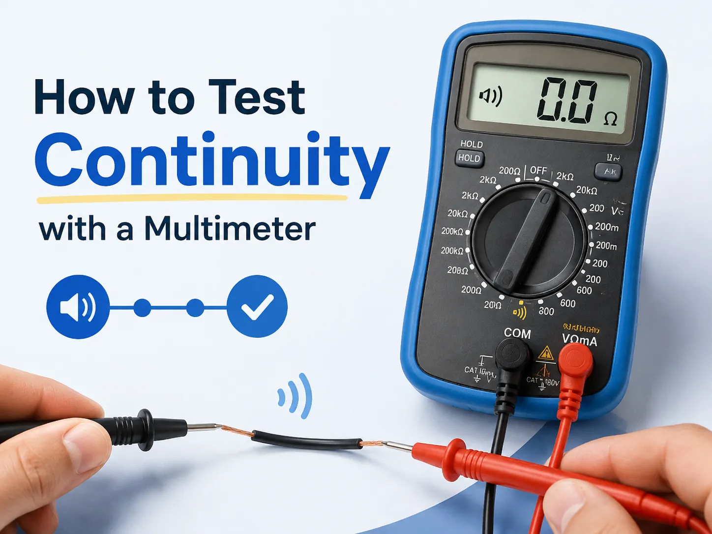
What Is a Continuity Test & Why It Matters
Continuity refers to the ability of an electrical circuit to remain uninterrupted between two points on the circuit. A continuity test is a test to check how electricity flows between two points in the electrical circuit. If a continuous path exists, the current flows through it and the meter either beeps or shows almost zero ohms. If there is no complete path (for example, a broken wire, or blown fuse or an open switch), the current cannot flow through the path and there is no sound from the meter (it shows OL).
Importance of continuity tests: it is the quickest way to check for continuity without requiring power at any point. Continuity tests are commonly used:
- To determine if there is a broken wire in the cable.
- To ensure that the fuse is intact before it is replaced.
- To ensure that the switch or relay contact opens when it is turned on.
- To identify which wire conductor in the multi-core cable is which.
- To check the earth/ground bonding continuity.
- To ensure that the crimping or soldering of the connector or terminal is done correctly.
What You Need Before You Start
The test itself takes seconds; the preparation takes a minute. Have these ready:
| Item | Why You Need It |
|---|---|
| Digital multimeter (DMM) | The tester itself; any basic DMM has continuity mode |
| Two test leads | Red and black, with probes; these plug into the meter |
| Known-good reference | A short piece of wire, or touch the probes together — to confirm the meter works |
| Fresh or charged battery | Low battery gives false readings; many meters show a battery icon |
| Insulation/tape or clips | To hold probe tips steady on the test points |
The only skills you will need for this is to read the meter and execute the steps outlined below. Following safety rules is essential, since continuity testers and live current should never mix.
Safety First: The Rules That Never Change
- Switch off the circuit. Continuity tests work by sending a negligible current through the circuit – there is no need to do them on live electrical power. It is necessary to switch off the breaker or disconnected the circuit before carrying out the test with the help of the voltage tester or accordingly configure the meter in a mode to measure the voltage.
- Discharge capacitors. The capacitors that can store electrical energy act as suppliers of the current through your leads. Discharge large capacitors before carrying out a test.
- Disconnect at least one ball of the cable. If you need to check one wire, you need to disconnect it from the circuit otherwise it is possible to get misleading information due to the functioning of other components.
- Do not verify continuity on working equipment. Continuity checks do not involve the transmission of electric power through the circuit and can cause the damage of the meter.
The Continuity Symbol on a Multimeter
In most cases, digital multimeters have a continuity function sharing the slot with the resistance function, which is signified by a symbol that resembles:
- The sound wave icon in the form of the curved line with multiple radiating waves (the common IEC symbol for the “audible continuity”), or
- The ohm symbol (Ω) with a sound wave icon or without, or
- The ohm symbol only (Ω) — in uncomplicated devices, continuity occurs in the lowest resistance range.
If your device contains a separate continuity setting (most probably with a sound wave symbol and sometimes with a speaker sign), turn the device there — the signal will automatically sound off. If there is no continuity setting, set it to the lowest resistance setting (of the level of about 200 Ω).
Step-by-Step: How to Run the Test
The whole process can be illustrated with these steps:
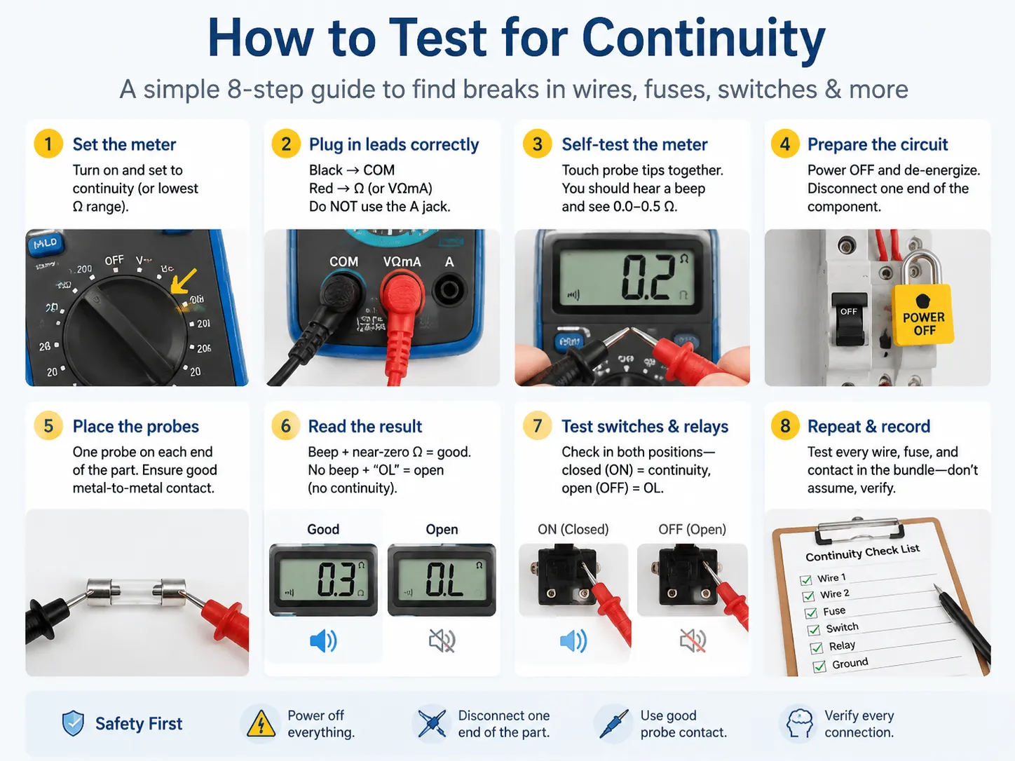
- Turn the multimeter on. Then set it onto the continuity function (or the lowest Ω setting). Proceed with inserting the wires. In other words, you need to insert a black wire into the jack called C and a red wire into the jack called Ω (or VΩmA). Do not insert the wires to the jack for amps.
- Ensure that the multimeter is working correctly. To do this, you need to touch both ends of the probes. If everything is correct, a sound will appear and zero resistance will show on the display (0.0-0.5 Ω). If nothing happens, you need to check the condition of the wires, battery, as well as the dial position.
- Make the circuit safe by following the safety procedures — turn off the power and pull one end of the wire.
- Now, you can touch the probes to the two points which you want to check.
- Look at the result. If there is a sound and the meter reads zero, you can state that there is continuity. If the meter does not beep and shows OA, you can say that there is no continuity.
- For relays and switches: check both positions of the switch (closed (ON) and opened (OFF)).
- Name what you found and repeat the procedure for all wires.
How to Read the Results: Beep, Ohms & OL
Three possible outcomes, and each means something specific:
| Display | Meaning | Interpretation |
|---|---|---|
| Beep + 0.0-0.5 Ω | Perfect continuity | The path is intact — short, solid connection |
| No beep + small number (e.g., 2-50 Ω) | Continuity with resistance | Path exists but is degraded — corroded contacts, long run, thin wire; investigate for critical circuits |
| No beep + “OL” or “1” | Open circuit / no continuity | The path is broken — blown fuse, snapped wire, open switch, bad solder joint |
It’s good to know two particulars about digital meters: some read “OL” (Overload) and some read “1” as signs of an open circuit. This just means the resistance is above the measuring capability, meaning it’s a case of “infinity.” Similarly, the continuity setting on some meters may beep on readings that indicate a low resistance (generally around 30 ohms or so), so don’t take the beeping for granted.
What Ohm Reading Means What
Provided you’re running tests in resistance mode as opposed to the beep mode, this is how to gauge the numbers:
- 0.0 Ω — perfect short circuit: the best opportunity for a short wire, switch contact, or fuse.
- Under ~1 Ω: good continuity reading — quite typical when working with short wires and closed contacts.
- 1-10 Ω is still considered continuous, but a question could arise as to the implications regarding the length of the wire used, connector, possible minor corrosion, etc.
- Above 10-50 Ω: an airline reading is likely indicative of degradation/risk — due to corroded and dirty contacts, partially damaged wire, bad soldering. If this reading results from testing power and grounding circuits, this is considered a red flag.
- OL (infinite reading): zero connection — open circuit.
Does a reading of 1 ohm translate into no continuity? Of course not, it is a low-resistance figure indicating a good continuity. The only instance of “no continuity” would be where a reading of OL/infinite resistance would appear. However, it is important to note that there is a slight possibility that out of a very long distance run of wires and bad contacts, the resistance is higher than 1 ohm.
Practical Tests: Wires, Fuses, Switches, Cables
Four simple tests, done in the same way:
- Fuse: test each end cap. A beep means the fuse is okay, while OL means blown. This test answers the question, “Does 1 ohm mean no continuity?” A good fuse will have a reading near 0 Ω.
- Wire/cable core: test each end of the wire. When dealing with a multi-core cable, it is important to test each core as well as check between cores to ensure there are no shorts (OL means good insulation).
- Switch/relay contact: test the two terminals. Press the switch. When the switch is closed it should beep and when it is open that should register as OL. If it beeps in both positions, the contacts are fused shorted. If it never beeps, the contacts are defective.
- Earth bonding: test between the bonding conductor and earth bar. Low ohms confirms that the connection is intact.
Troubleshooting a Multimeter That Won’t Test
| Symptom | Likely Cause | Fix |
|---|---|---|
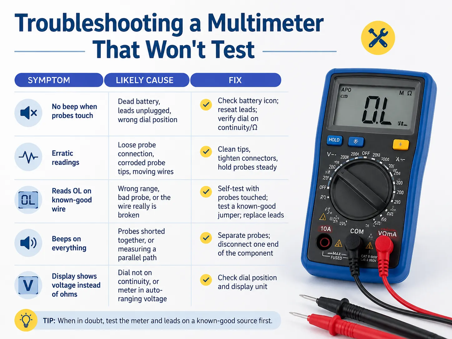
| No beep when probes touch | Dead battery, leads unplugged, wrong dial position | Check battery icon; reseat leads; verify dial on continuity/Ω |
| Erratic readings | Loose probe connection, corroded probe tips, moving wires | Clean tips, tighten connectors, hold probes steady |
| Reads OL on known-good wire | Wrong range, bad probe, or the wire really is broken | Self-test with probes touched; test a known-good jumper; replace leads |
| Beeps on everything | Probes shorted together, or measuring a parallel path | Separate probes; disconnect one end of the component |
| Display shows voltage instead of ohms | Dial not on continuity, or meter in auto-ranging voltage | Check dial position and display unit |
Continuity vs Resistance: When to Use Which
Continuity mode and resistance mode are siblings; they use the same measurement but present it differently:
| Feature | Continuity mode | Resistance mode (Ω) |
|---|---|---|
| Output | Beep + display | Number in ohms |
| Best for | Fast yes/no checks (wires, fuses, switches) | Measuring actual resistance values (coils, sensors, heater elements) |
| Threshold | Beeps under ~30 Ω (typical) | Shows any value up to the range |
| Typical use | Quick troubleshooting | Component testing and diagnostics |
Continuity is used for the “is it connected” questions, while resistance mode should be used for situations that require a true measurement, such as verifying the specified resistance of a motor winding or heater. In automated manufacturing making extensive use of connections and resistance measurements, these two concepts — verifying connections and measuring resistance — are some of the things that automatic test lines do thousands of times every day, and understanding them is essential for the debate between manual and automatic testing methods.
Frequently Asked Questions
What is a bad reading for continuity?
A continuity reading is considered bad if it presents a reading of open or marginal when it should indicate good continuity. “OL” (infinite resistance) means the continuity is nil; i.e., something has broken the circuit, such as a broken wire, blown fuse, or open switch. Connectivity measurements greater than 10-50 ω in a short circuit should also be watched for since these readings may indicate corrosion, bad contacts, or partially broken wire. In case of a short wire or closed switch, the expectation is to measure approximately zero ohms or very close to that.
What is the symbol for continuity on a multimeter?
The continuity sign resembles a sound wave, which is a curved line that has little arcs coming off it. This sign is often placed alongside the ohm sign or speaker sign. Meters that do not have a separate continuity function use the lowest resistance level. Sometimes there is the word “CONT” printed next to the continuity symbol or a diode sign nearby, so check the meter markings and the user manual.
What is the correct ohm reading for continuity?
If a good connection is established through a wire, contact closure or fuse, the reading should be around zero ohms (usually 0 – 0.5 ohms accompanied by beeps). For longer distances or where connectors are used, readings of up to a few ohms will be acceptable. The critical point to note is that any reading that is not infinity means that the continuity is intact, and “OL” (infinity) means the circuit is incomplete.
Does 1 ohm mean no continuity?
No-1 ohm means superb continuity. A low resistance like 1 Ω indicates that current can flow freely through it, which is precisely what one expects for a wire, fuse, or closed switch. “No continuity” is denoted only by OL (overload/infinite resistance). In fact, 1 Ω is only high for a very short and thick conductor, yet it still indicates that the path is intact.
References
- Fluke — What Is Continuity and How to Test It
- IEC 61010 — Safety Requirements for Electrical Equipment for Measurement
- NFPA 70 (NEC) — Testing and Maintenance Requirements
- Keysight — Multimeter Fundamentals and Resistance Measurement
- OSHA — Electrical Safety and Testing Practices
- Eaton — Electrical Testing and Troubleshooting Guides
Conclusion
Among the many things you will learn when you study electrical work, testing continuity is probably the most valuable skill you could possibly acquire in the field: de-energize your circuit, set your multimeter to the continuity setting (or to the lowest Ω setting), check its own probes, put your probes at the two test points, and retrieve your results. If you get a beep and read near zero ohms, it means you have continuity; OL indicates that the circuit is open; any number in between indicates the circuit is faulty. You will be able to analyze circuit problems without fear after mastering continuity.On the production floor, that same verification logic scales up into automated test systems — the payback analysis of fully automated vs semi-automated lines and the efficiency numbers in our industrial automation efficiency overview show why connection testing at scale is a factory’s best friend.