benlong


Electrical Insulation Resistance Test
The part of an electrical circuit that usually happens to deteriorate very slowly and eventually fail at an unexpected moment is known as insulation. A winding of a motor, a power cable and the internal barrier of a breaker either performs the separation function properly or not. The point is, the difference between a safe and unsafe installation in terms of insulation is usually measured by the insulation resistance threshold of either circuit. An insulation tester provides you with an opportunity to check how far the installation has gone down the waste. By applying a small DC voltage across pieces of insulation one can measure how much the insulation is able to hold.
Simple answer: Insulation resistance testing utilizes a DC voltage that is applied through the insulation layer in order to gauge the amount of leakage current as it is measured in mega- or gigohms. The nominal test voltages are: 250 V (low-voltage control circuits), 500 V (low-voltage equipment rated at 230/400 V), 1,000 V (cables and motors rated at voltages of up to 1 kV), and 2,500 – 5,000 V (equipment rated at medium voltage). It is necessary to wait 60 seconds before performing the measurement. In most cases 1 MΩ is typical for low-voltage circuits. For rotating machinery it varies from 1 MΩ to additional 1 MΩ for every kV of rated machine voltage at 40C according to IEEE 43; in case of a new piece of equipment it should show the insulation resistance of above 100 MΩ. The polarisation index should exceed 2.0 (calculated using 10min result divided by 1min). If the result is below 1.5, it should indicate moisture or contamination.

What an insulation resistance test actually measures
The test is easy to understand, but it is also often misconstrued. To perform the test, a known DC voltage is applied either between a conductor and the ground or between two conductors and the insulating material is found to allow the small current flowing through it to be measured. Due to the very low amount of current present during the measure of insulation – nanoamps to microamps for good insulation – the resistance obtained is very high, which is the reason why the results are expressed in megohm or gigohm rather than ohm, and why regular multimeters cannot perform the test in the first place. Regular DMM measures resistance by applying a low voltage into the circuit that has no power to say anything about the insulation system.
What the test should be determining is not some arbitrary value but rather a difference from an expected value. Insulation can be spoiled with moisture, heat, contamination, mechanical damage, and partial discharge process, all of which significantly lower the resistance of insulating material. So when the insulation is good the resistance value is sufficiently high, thus proving that the insulation is working at the moment of the measurement; but when the resistance has dropped by half since the last measurement that means the insulation has deteriorated, which is much more important in this case and a reason why this test should be part of monitoring process rather than an isolated event.
Why the test uses DC, and the three currents involved
Insulation acts differently than resistance. When a DC voltage is applied, there are three curcents present – knowing about these currents sheds light on almost all practical aspects of the testing process.
- Capacitive charging current. The insulation system acts like a capacitor; it means that the initial capacity is very high, but it fades away in a few seconds.
- Dielectric absorption current. The molecules of insulation behave accordingly with the incoming electric field. This current quickly fades away in few minutes, but it is the one why polarization index is effective.
- Leakage or conduction current, which is steady state current flowing in the resistance of the insulation.
Since both first currents accompany the third one, the reading can be taken only after some time after the voltage is applied, which means that it would reflect the currents that take place in the first two cases. Thus, it became a common practice to record the data after at least 60 seconds.
Test voltages by equipment class
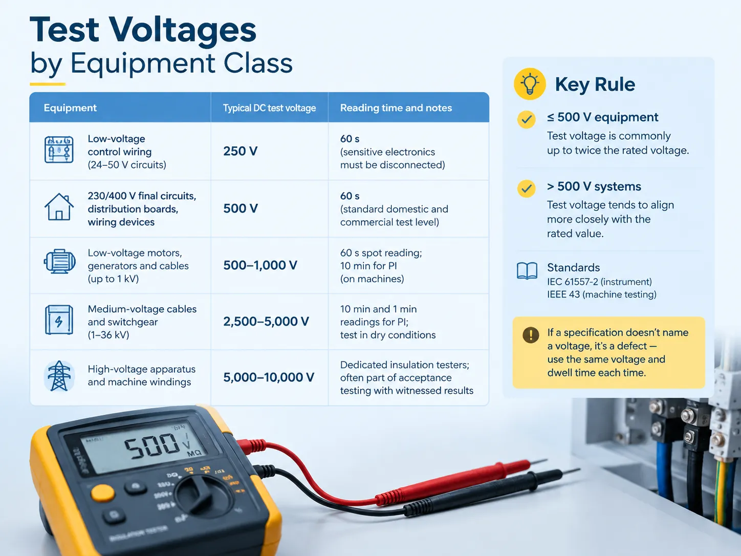
The voltage used for testing needs to be sufficiently high to detect any weaknesses yet sufficiently low to avoid damaging insulation that is already in perfect condition. The actual voltage used may differ between the various options available, as this is connected to equipment that is being used to carry out the tests.
| Equipment | Typical DC test voltage | Reading time and notes |
|---|---|---|
| Low-voltage control wiring, 24-50 V circuits | 250 V | 60 s; sensitive electronics must be disconnected |
| 230/400 V final circuits, distribution boards, wiring devices | 500 V | 60 s; the standard domestic and commercial installation test level |
| Low-voltage motors, generators and cables up to 1 kV | 500-1,000 V | 60 s spot reading; 10 min for polarization index on machines |
| Medium-voltage cables and switchgear, 1-36 kV | 2,500-5,000 V | 10 min and 1 min readings for PI; test in dry conditions |
| High-voltage apparatus and machine windings | 5,000-10,000 V | Dedicated insulation testers; often part of acceptance testing with witnessed results |
One common convention that should be remembered in any specification is that equipment rated at or below 500 V is typically tested at a voltage of as much as twice the rated voltage. In the case of equipment rated higher than this voltage, the test voltage is usually somewhat closer to the rated voltage. The main standard for this type of instrument is IEC 61557-2 and the standard for machine testing is IEEE 43. When no voltage is mentioned in the specification, this is considered a defect in the specification rather than the installer’s choice — it is the same voltage used each time along with the same period of time or the trend will be distorted.
What is worth testing, and how often
It isn’t only cables that require testing; in fact, whenever two conductors encounter a dielectric in which they are separated from one another, testing is required. Each kind of equipment has its own unique testing cycle. The motors operating the pumps, mixers, grinders, fans, compressors, and all refrigeration units are well-known examples because these types of apparatus become defective by moisture and due to heating/cooling cycles. Any problem in one of the windings instantly causes the stopping of the whole production line. Cable testing takes place at the moment of installation and later on as needed, particularly if the cable lies underground, is wet, or is exposed to open air. Switchgear completes insulation testing during acceptance and after any repair. Transformer testing includes oil testing and checking of winding insulation at the same time. And finally, devices such as breakers, contactors, and sockets need to undergo dielectric integrity tests both during the type testing and together with all units manufactured in the shop.
There are two available time-related aspects considered in any practical implementation scheme. First of all, the measurement should be carried out either when the equipment is new (or renewed) so that the achievements in equipment degradation can be assessed. The arranged stop of the devices makes testing feasible, since testing requires machines to be switched off, isolated, and unloaded. Reading a background on planning a manufacturing plant shutdown explains why those windows are the right place for the whole electrical test schedule rather than for one asset at a time.
The test procedure, step by step
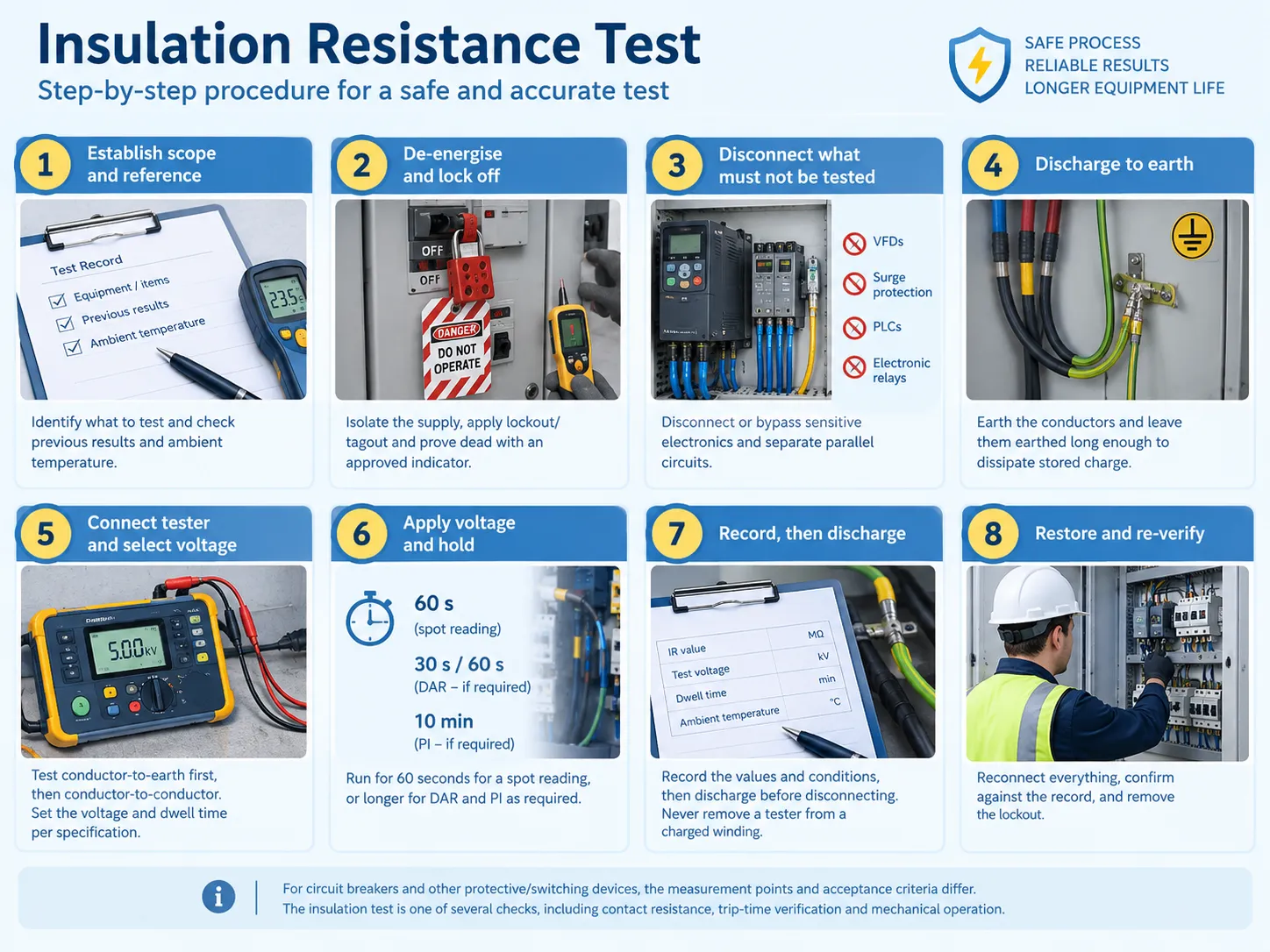
The insulation resistance test is conducted under high voltage and on equipment which is normally live. This method is the absolute minimum one; many local codes and local site instructions will make additions to it, and none of the points mentioned can be excluded.
- Define the limit and the reference. Identify all components which are to be checked and get the previous results along with the ambient temperature when the measurements were taken.
- Disconnect and lock. Switch off the supply, apply lockout/tagout, and ensure that the installation is dead with the use of the approved voltage indicator.
- Disconnect the items not to be tested. Electronic devices, VFDs, surge protection devices, PLC modules, and electronic relays must be disconnected, as the test voltage will damage them. Avoid connecting parallel circuits so that you get the measurement you intend to get.
- Earth disconnection. Capacitive charge stored in long cable runs and windings, can be lethal; that is why it is necessary to earth the conductors and hold them at earth for a long time.
- Connect the tester and choose the test voltage. Test conductor to earth first, and then conductor to conductor if required. Set the voltage within the framework of the specification.
- Apply the voltage and wait. Run for sixty seconds in case of the measurement, or run for ten minutes in case of polarization index.
- Make records and earth beforehand. Write the value down along with the voltage, time and ambient temperature. Do not remove the leads without earth the equipment.
For individual protective and switching devices, the specific measurement points and acceptance criteria differ from those of a cable or a winding. The insulation test is one of several checks a breaker has to pass, alongside contact resistance, trip-time verification and mechanical operation, and the full set is described in a guide to testing a circuit breaker for anyone assembling a commissioning procedure.
What counts as a good reading
It is incorrect to state that a single number exists to describe a specific aspect of a product. There is a set of different parameters that tells us about the capabilities of certain type of instruments under precise conditions, and the challenge lies in knowing what exactly benchmark should be used.
| Benchmark | Value | Applies to |
|---|---|---|
| The one-megohm rule | ≥ 1 MΩ | General low-voltage circuits and equipment; a minimum, not a target |
| IEEE 43 minimum for rotating machines | Rated voltage in kV + 1 MΩ, at 40°C | AC and DC machine windings; a 400 V motor therefore needs at least about 1.4 MΩ |
| New or newly rewound machine | Often > 100-1,000 MΩ | Commissioning baseline for motors and generators |
| New installation cables and wiring | Commonly > 100 MΩ | Acceptance testing; low values indicate moisture or damage |
| Polarization index | > 2.0 good; 1.5-2.0 questionable; < 1.5 poor | Machines and long cable runs; not meaningful below about 1 MΩ |
| Dielectric absorption ratio (60 s ÷ 30 s) | ≥ 1.4 acceptable | Quick alternative to PI when a 10-minute test is impractical |
There are two notes against that table. First, a high figure does not mean that the insulation is adequate; the insulation system at the end of its life may give good readings under dry conditions but fail after a week of rain. This is why moisture conditioning and trending are important. Second, a low reading is not always indicative of a defect. Contamination at the surface of bushings and insulators, water in a junction box, or an instrument that was left in contact with the conductor during the test can lead to getting a low reading for sound insulation.
DAR and PI: when one number is not enough
The dielectric absorption ratio (DAR) is the resistance at 60 seconds divided by the resistance at 30 seconds. The polarization index (PI) is the resistance at 10 minutes divided by the resistance at 1 minute. Both take advantage of the fact that absorption current dissipates slower in dry, clean insulation as compared to the insulation contaminated with moisture and deposits.
The good condition machinery shows the PI of 2 or greater since the current decreases between the one minute mark and the ten-minute mark leading to growing ratio. Moisture- or contaminant-filled insulation reaches its steady-state leakage current almost immediately making the ratio flat and even lower than 1. The widely acknowledged threshold values are: above 2.0, good condition; from 1.5 to 2.0, should be investigated; below 1.5 indicates a problem which might or might not be solved by drying and cleaning. The only restriction here is that PI becomes meaningless below around 1 MΩ of insulation resistance due to dominance of leakage current over absorption; thus, check simple resistance first and only then consider using the ratio.
Temperature, humidity and the corrections that make readings comparable
The insulation resistance is heavily impacted by the temperature and the formula involved in this is strong enough to cause a naive observation to seem like a wrong comparison. For every temperature rise of 10°C above the baseline temperature, roughly halve the insulation resistance value, and for every 10°C below the baseline temperature, the insulation resistance value will vice versa double it. Thus, if an insulation resistance measurement reads 200 MΩ before at 15°C, and then it shows 100 MΩ in summer at 25°C, it is not a sign of degradation but an indication of pure following of the dependency curve.
IEEE 43 deals with this issue by requiring insulation resistance measurements to be taken and corrected at reference temperature of 40°C which creates a possibility of comparing the measurements throughout the seasons etc. In practice a correction curve is applied for the insulation class and actual values obtained after measurement with the correction curve applied are tracked. As humidity is also a factor in this case but is less controlled.
Five mistakes that produce misleading results
- Failing to discharge before and after taking the readings . A charged cable or winding has dangerous voltage post-test. The danger is for the technician and data error is due to the testing having been done on a live circuit.
- Having the equipment connected. VFDs, surge protectors, PLC input modules, and electronic relays are not built to handle test voltages and getting damaged or shunt the measurement thus resulting in a low reading.
- Testing for a short time. A five-second read actually measures charging current. In this way, there is nothing that can be somehow correlated to it and trend will be noise.
- Disregarding temperature. Getting a figure without stating the temperature at which the figure has been obtained does not make it a good historical series; and historical series is the reason of the test.
- Reliance on one reading. Insulation testing is about trends. One figure without baseline or history is not able to distinguish stable and faulty system.
Megohmmeter or hipot tester: not the same instrument
Megohmmeters and hipot testers are usually misinterpreted as the same, however, they are two different tools with fundamental differences. A megohmmeter, also referred to an insulation resistance tester, tests insulation through application of a specific DC voltage, measuring the amount of leakage current and providing readings in the form of megohms. The megohmmeter is a diagnostic tool that is not harmful, if used in a proper way, and it is suitable for field testing, commissioning and trend performance analysis.
Hipot testing, on the other hand, is the method of applying HV voltages and ensuring the reliability of insulation. A hipot tester applies much higher voltage – according to IEC standards, it should be equal to two times the operational voltage plus 1,000 V – for the specific period of time, usually one minute, and verifies whether the application of this voltage will lead to the leakage current within the limits set by standards. It helps to define whether the insulation is capable of withstanding voltage stress or not, and it can destroy faulty insulation. That is why hipot testing is supposed to be conducted in a properly controlled environment, instead of using it in the field.
From a single reading to a programme: baselines and trending
Insulation testing is valuable in terms of comparison rather than measurement. A program consists of four components: a baseline measurement during commissioning in which test voltage and dwelling time are noted; a standardized testing process so that every test is comparable with prior tests; a record keeping system recording the voltage, time and temperatures; and fact that an overall trend of insulation condition is monitored rather than the absolute value.
The most common practical alarm rule at any site is that insulation has dropped down by over 50% from its baseline value or its polarization index became lower than 1.5. Neither is enough to trigger any specific repairs, but both require an investigation into the insulation status including cleaning, drying and retesting if the situation calls for it. Thus, insulation regularly tested in this manner is repaired according to an established schedule whereas insulation that is not tested fails unexpectedly.
Insulation testing in production: from sampling to every unit
The effectiveness of the entire process depends on the same factors regarding equipment that is already installed. While on production line, it transforms into a quality gate, and the question becomes “how many products to test and why.”
Sampling inspection serves as the traditional solution, whereby several samples in a lot are tested and the assumption is made that the rest are the same. The philosophy works when the process is stable, and no major damage will occur in case a defect appears. However, it fails at the critical point of its application, because it neglects the faults that occur regularly only at specific point — such as problems with contamination of moulding, insert, and barrier disturbances. The distinction between sampling and 100% testing, and the conditions under which each is defensible, is the subject of manual and automation testing compared, and the conclusion for safety-critical components is consistent: the defect you did not test is the one that reaches the customer.
Why a protective device cannot be sampled
If the product in question is a protective device, dielectric strength is a necessary feature. A circuit breaker or an RCD that fails an insulation test will not isolate a fault effectively, resulting in the inescapable necessity of recalling a batch that was sampled rather than actually tested. This is the main reason why mass producers of electrical components perform the dielectric and insulation resistance tests in-process, testing each unit in the course of production.The economics of that move are not speculative; the payback arithmetic of moving from manual sampling to 100% automated testing of miniature circuit breakers is worked through in an analysis of automated versus manual MCB testing payback, and it turns on three numbers: the cost of the test itself, the cost of a field failure, and the reduction in downstream rework when defects are caught at source.
What an automated line has to do with the test data
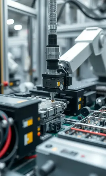
Changing that aspect impacts much more than just the test station. The data gathered from each unit must be recorded, connected to its uniqueness, and preserved for the purpose of tracking. The parameters must also be confirmed so that the operator won’t change them to make sure a defected unit passes the test. Furthermore, there must be a line drawn so as to let the dielectric tests happen after assembling and before the packaging of the unit to detect failures earlier. What a fully integrated line looks like in practice — assembly, calibration, dielectric test and final functional check running as one sequence with results logged per unit — is illustrated by the configuration of an MCB automatic production line, which is the category of equipment benlongkj builds for electrical-component manufacturers.There’s a relationship that exists whether a plant is testing motors in the field or breakers on line – use the same principle; fix the method, collect the information, and evaluate the results.
FAQ
How do I test the insulation resistance of an electrical circuit?
First, disconnect and isolate the power supply cable from the network. Ensure that there are no live wires – if any conductor causes danger to home appliances, disconnect them. Also, discharge underground wires into the ground. Set an insulation resistance tester by connecting it to a wire below the ground ensuring the correct voltage is selected — 500 V for a 230/400 V circuit or 250 V for low-voltage control circuit. Wait a few seconds before taking the reading. Repeat the test before unplugging the tester.
What is a good Megger reading on wire?
When it comes to wiring that operates below the usual 1000 volts, we can say that anything above 1 megohm means that it satisfies the common standards, however, this must be a level much above 100 MΩ for acceptable wiring. If measurement shows values below 1 MΩ that indicates a defect like moisture, or damage which means cleaning and drying followed by another test. When making comparisons, the best practice is to compare the readings you get now to previous readings for the same circuit, measured at the same temperature.
What is a good insulation resistance test result?
The answer depends on the class of the equipment. Low-voltage circuits requires at least 1 MΩ, while for newly installed low voltage equipment the insulation resistance measurement will usually be above 100 MΩ. The required insulation resistance for rotating machines is equal to the voltage value in kilovolt plus 1 MΩ (as per IEEE 43 and after adjusting for 40 degrees Celsius) for machines with P.I. more than 2.0. Typical insulation resistance values for new generated equipment are in megohms.
Is an insulation resistance test the same as a Megger test?
In practical terms, the answer is yes, but when it comes to the technical use of the word, the answer is no. A megger is a name given to the insulation resistance tester but, in reality, the two refer to the same type of measurement. An important definition to keep in mind is the difference between a hipot test and a megger test. The hipot test uses a high voltage electrical charge to test electrical insulation while the megger uses a given amount of voltage to measure resistance.
How often should insulation resistance be tested?
Every year for critical motors and generators, and at every scheduled shutdown for the electrical distribution system, the test process is employed. Since the test requires de-energization and the discharge process, the test can be performed during planned outages. The best practice is to create a baseline at installation and to conduct the tests at regular intervals with the same rate of voltage and curing time. The same test should be done after an intervention is performed if possible.
References
- IEEE — IEEE 43: Recommended Practice for Testing Insulation Resistance of Electric Machinery
- International Electrotechnical Commission — IEC 61557-2: Insulation Resistance Measuring Equipment
- International Electrotechnical Commission — IEC 60243: Electric Strength of Insulating Materials
- Fluke Corporation — Guide to Insulation Resistance Testing and Data Trending
- Vitrek — Basics of Insulation Resistance Testing
- Weschler Instruments — Insulation Testing: Megohmmeter or Hipot Tester
- OSHA — Electrical Safety-Related Work Practices, 29 CFR 1910 Subpart S
Conclusion
The significance of the insulation resistance test in electrical maintenance lies in the fact that it is the cost-effective method of predicting potential failure. The process consists of applying a certain DC voltage, waiting for charging and absorbing currents to cease, measuring leakage value, and providing with a resistance level provided that it is not used for independent evaluation, but mainly for comparison with the same test done in the same context earlier. The voltage has class, hence, it may be selected among 250 V, 500 V, 1,000 V or more; the reading is done at 60 seconds for a snapshot value and at 10 minutes for a polarization index with a correction factor accounting for 40°C; in compliance with that approach, the trend should be examined and not just the number itself. Upon the introduction of the above-explained method, it may be scaled from a plant-pump engine to an assembly line moving every switch that it produces through a dielectric treatment: set the method, register the conditions, and record the data over time.