benlong


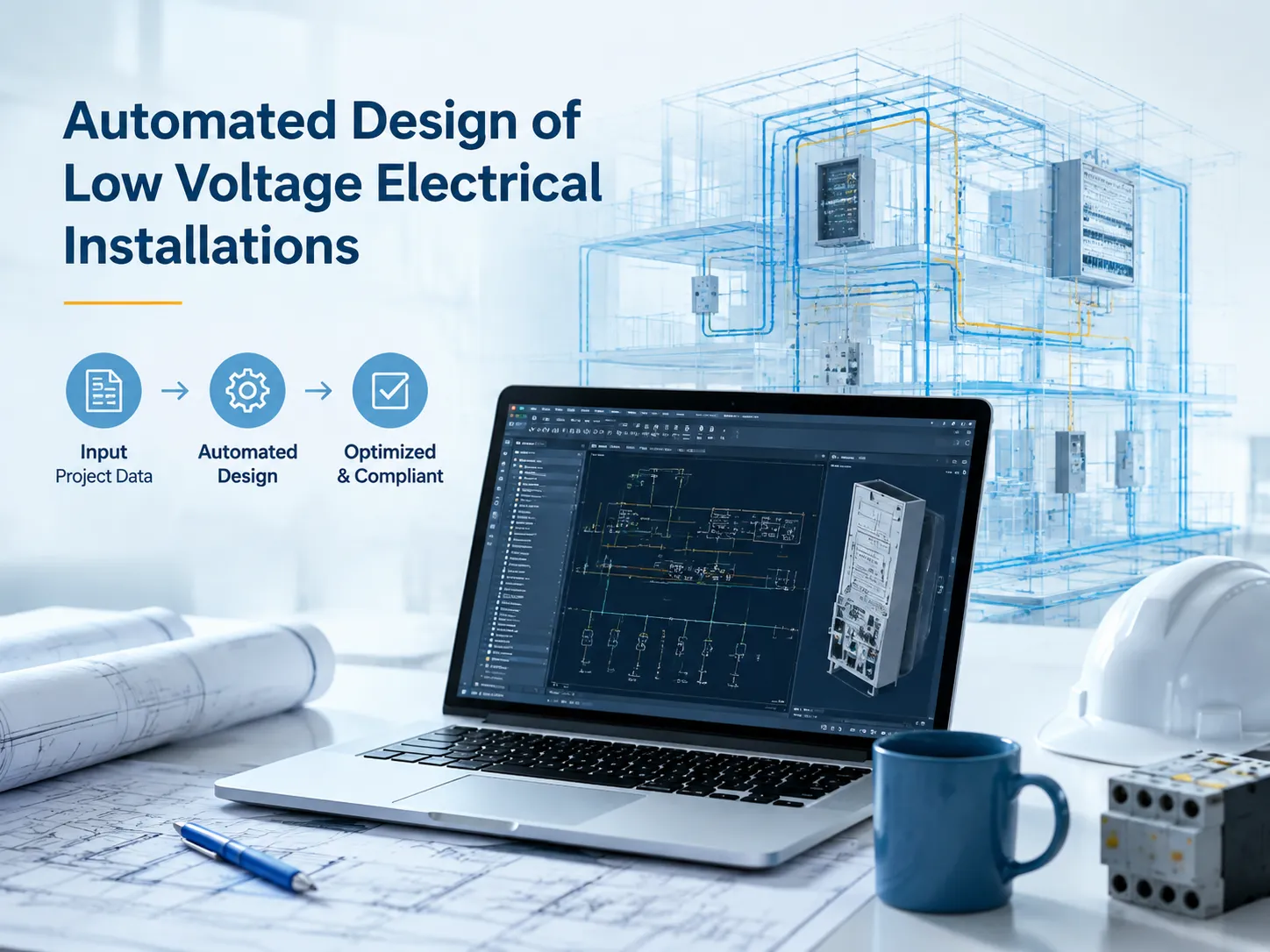
Automated Design of Low Voltage Electrical Installations
Traditionally, designing low-voltage electrical systems was an arduous and time-consuming process that consisted of weeks upon weeks of engineering schematics, checking circuits, and ordering hardware from meticulous lists made in spreadsheets. The advent of automated tools for designing low-voltage systems has considerably changed the situation. Automated software now allows for automatic creation of diagrams, selection of equipment, calculation of cables, and making layouts of electrical panels with possible time savings in the region of 30-70%. That is why the advent of this technology represents a great step in the development of engineering for the generation of newly-trained engineers, panel makers, and manufacturers.
This text attempts to provide more complete information about the technology of automated LV design.
In summary: The automated design of low voltage electrical installations is about using electrical CAD/CAE platforms (like EPLAN Electric P8, AutoCAD Electrical, SEE Electrical, etc.) together with the use of a device library and specification data to automate the process of generating electrical designs.
What Is Automated LV Electrical Design?
The automated design of low-voltage electrical systems is the use of electrical engineering software (electrical CAD or CAE) for designing, verifying, and implementing electric designs in an automated fashion rather than creating charts and connections manually. When talking about low-voltage systems, we refer to the IEC definition meaning electric installations of up to 1,000V AC (or 1,500V DC) — these can be electric distribution cabinets, motor control centers (MCCs), machine controls, switchgears, etc.
Aspects that can be automated:
- Creating schematics — the creation of diagrams through inserting symbols and connecting them, as well as numbering wires is done automatically.
- Verifying design rules — the software checks the possibility of the connection of devices and whether they comply with the standards
- Selecting and sizing devices — it is possible to choose devices from manufacturers’ databases with the use of rule-based sizing (for instance, the calculations for coordination of protections).
- Placing devices in a panel or box — this refers to establishing the layout of devices on 2D or 3D panels considering distances and thermal characteristics.
- Producing documents — the process of terminal diagrams, circuit descriptions, cable paths, materials lists, etc. is carried out automatically.
The result of this approach to the design is that engineering personnel as a whole make decisions while software performs the accounting function where most of the mistakes were made earlier.
Why It Matters: The Manual Design Problem
Manual LV design has three chronic problems that automation directly attacks:
| Problem | Consequence | How Automation Fixes It |
|---|---|---|
| Connection errors | Wrong wires discovered at panel testing | Auto wire numbering + design rule checks catch them in design |
| Documentation drift | As-built differs from drawings; maintenance headaches | Documentation generated from the model — always in sync |
| Slow, repetitive work | Weeks per project; engineers burned on re-drawing | Libraries + reuse cut design time 30-70% |
| Inconsistent standards | Each engineer draws differently | Company templates enforce one standard |
| Part-list mistakes | Wrong devices ordered | BOMs generated from placed devices — no transcription |
The cost of mistakes made by companies manufacturing panels or equipment is costly twofold — once due to the reengineering of the design and once for failure of the equipment on the shop floor — underscoring the need for automated design to be integrated with automated manufacturing quality.
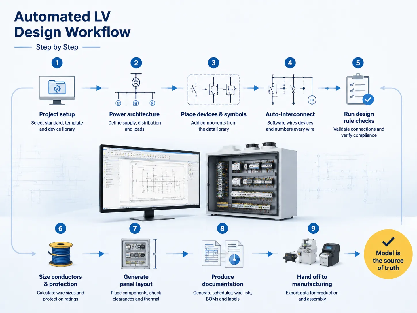
The Automated Design Workflow, Step by Step
The timeline of a commonplace LV design automation project consists of the following stages.
- Stage of project initialization involves defining standards and selecting a company template and library of equipment.
- During the electrification phase, the incoming energy, level of distribution, as well as consumption (loads: motors, lighting devices, heaters, control equipment) are defined.
- Steps of placing equipment and symbols consist of dealing with circuit breakers, controlling relays and automaton components as well as electronic equipment in accordance with data library information.
- The procedure of auto-wiring includes using software to connect devices automatically – binding of each wire is performed by macros which allows for completing the whole process in one go.
- The design rule checks must be followed to validate the connections from the design rule perspective, checking of open terminals, as well as confirming correspondence of protection devices.
- Conductors and protection devices are sized using rule-based tools – types of wires and ratings of protection devices are estimated on the basis of loads (standards IEC 60204-1, NEC charts, or manufacturers’ information).
- During the generation of the panel layout process, placement of devices into either a two-dimensional or three-dimensional installation, taking into consideration both clearances and thermal loads takes place.
- Documentation is generated automatically and includes terminal plans, cable tables, wirelists, BOM documents, and labels.
- The manufactured equipment is expected to be successfully exported from the computer in accordance with the standards used.
During every stage of the project development, it is possible to monitor the changes made to one of the two devices to ensure that the whole system of diagrams and documents gets updated simultaneously to avoid documentation gap.
The Main Software Platforms
The field is dominated by a handful of established electrical CAD/CAE platforms:
| Platform | Strength | Typical Users |
|---|---|---|
| EPLAN Electric P8 | Industry leader; huge device libraries, strong automation (macros, scripts), deep manufacturing integration | Panel builders, machine builders, industrial OEMs |
| AutoCAD Electrical | AutoCAD ecosystem; familiar interface, strong for schematics and smaller projects | Consultants, smaller panel shops, multi-discipline firms |
| SEE Electrical | Accessible pricing; good automation and library support | Mid-size panel builders, control specialists |
| EPLAN Pro Panel / SolidWorks Electrical | 3D panel layout and integration with mechanical design | Complex machines, 3D-integrated design |
| ETAP / DIgSILENT (power system tools) | Analysis-driven design (short-circuit, coordination, arc flash) | Power systems engineering, utilities |
EPLAN is currently the norm for electrical engineering, while AutoCAD Electrical is preferred in various engineering companies that are already utilizing Autodesk software. The selections that companies make often depend on their own systems and the nature of the work that they do.
Core Features That Do the Work
The power of automation is due to the following features:
- A device database with real information that includes manufacturer part data (such as vendor catalogs) and information about symbols, dimensions, ratings, and part numbers.
- Macros are pre-assembled standard circuits that can be inserted as a single unit that saves a lot of time in mechanical or electrical design processes.
- Automatic wire numbering means that every connection has its own number according to your numbering scheme.
- Design rules check (DRC) allows you to inject custom checks for missing parts and unconnected pins.
- Cross-reference management also prevents mistakes in cross-referencing connections contains coil-to-contact wires.
- RW-based management allows you to automatically generate terminal information directly from the schematic.
- A bill of material can be obtained with the help of a BOM report that contains part names and prices of the parts.
RW allows generating labels and wire numbers that can be printed in a production department.
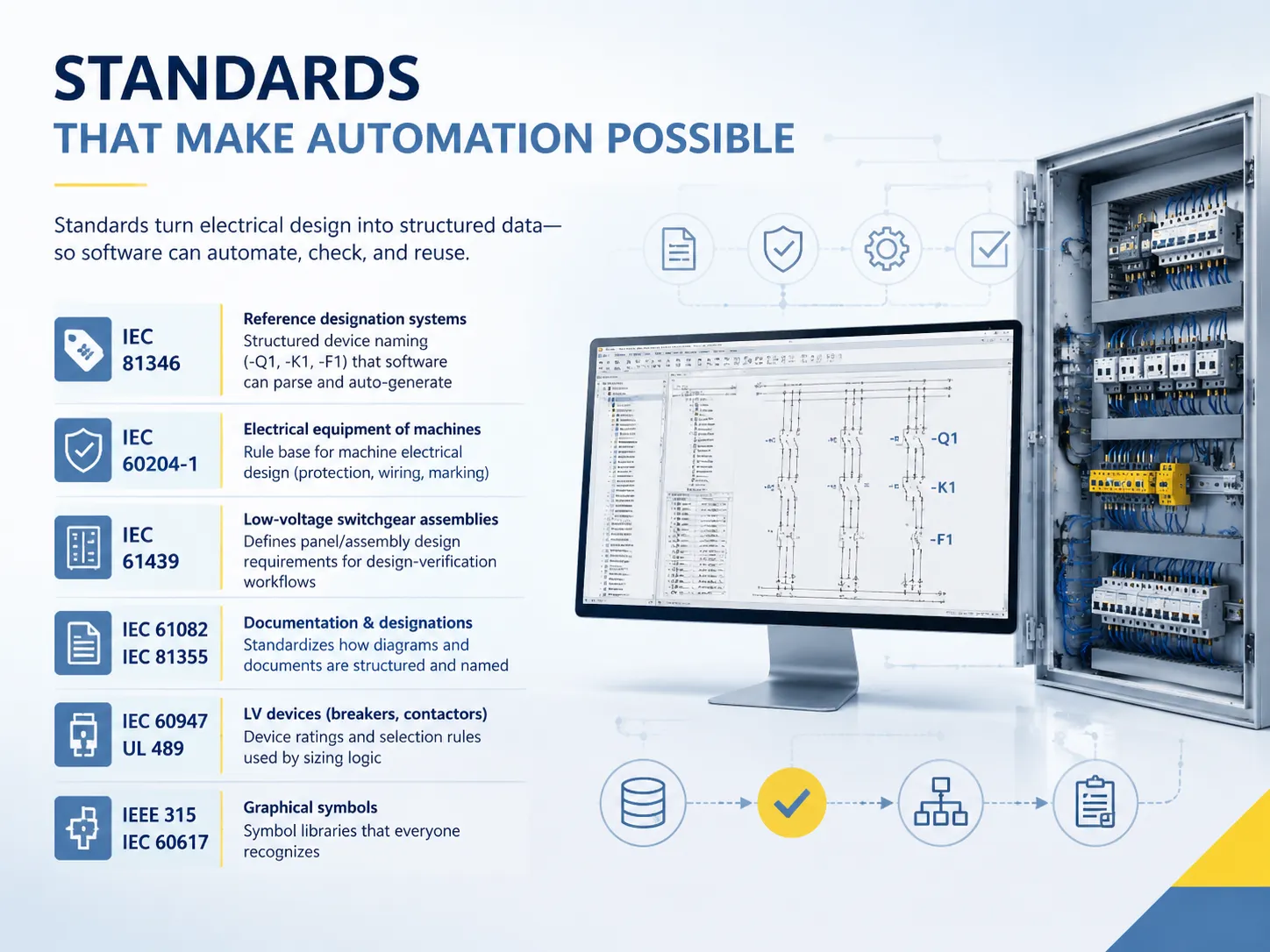
Standards That Make Automation Possible
It is because of the use of standards governing LV design that automation is made possible:
| Standard | Scope | Role in Automation |
|---|---|---|
| IEC 81346 | Reference designation systems | Structured device naming (-Q1, -K1, -F1) that software can parse and auto-generate |
| IEC 60204-1 | Electrical equipment of machines | Rule base for machine electrical design (protection, wiring, marking) |
| IEC 61439 | Low-voltage switchgear assemblies | Defines panel/assembly design requirements for design-verification workflows |
| IEC 61082 / IEC 81355 | Documentation preparation / designations | Standardizes how diagrams and documents are structured and named |
| IEC 60947 / UL 489 | LV devices (breakers, contactors) | Device ratings and selection rules used by sizing logic |
| IEEE 315 / IEC 60617 | Graphical symbols | Symbol libraries that everyone recognizes |
These are the standards that convert electrical designs from freehand graphical representations into structured data.
Device Data: The Foundation of Automation
How good the output of an automatic design will be is determined solely by the quality of the device data behind it. That’s why we should pay attention to the manufacturer ecosystems:
- The portals for device data, such as EPLAN Data Portal or CAD libraries from vendors, provide updated and validated data on parts (symbols, ratings, dimensions, part numbers).
- A device selected in the software brings into the design its real electrical data (in terms of sizing and BOM) based on the specifications of the respective manufacturer.
- When a manufacturer’s device library isn’t available, engineers build custom data — which is why working with component suppliers who publish complete electrical data (like circuit breaker manufacturers’ automation practices) makes design integration smoother.
- Data maintenance is important: outdated device data results in mistakes in the design measuring, as one of the few instances when automation fails due to data-related mistakes.
Designing for LV Equipment: From MCCs to Panels
Automated design covers all of the low voltage devices:
- Distribution boxes and distribution panels according to the IEC 61439 standard: connection to electrical network, bus bar systems, distribution of electricity to the users of electrical energy, and protection coordination – all done automatically.
- Motor control centers: including starter units, such as DOL, star-delta starters, soft starters and VSDs, all made of standard macros with automatic sizing of protection devices.
- Machine control panels according to the IEC 60204-1 standard: control circuits, PLC I/O, switches, actuators, safety circuits – wiring done automatically.
- Electrical fitting in large constructions: final distribution, electrical lighting and sockets are done automatically too.
From Design to Manufacturing: The Factory Handoff
For manufacturers, the advantage of using automated design is maximized because the information is fed directly into production.
- Wire processing: ready-made wire lists control the machinery used for cutting, stripping and crimping wires.
- Label printing: the wire numbers are printed from the same source database as the labels, so there is no difference between what is printed and what is shown in the drawings.
- Terminal assembly: terminal rail layouts and marking information are developed for the terminal assembly workbench.
- Testing: due to the automation of testing, the connection information is fed directly from the design to the testing machines and thus the results are reported based on the designs and not on the notes.
- As-built accuracy: since the model serves as the basis for all the production, the panel that is shipped is produced according to the model and hence there are no field discrepancies or warranty problems.
Measured Benefits: Time, Errors, Cost
Industry-reported results from automated LV design (typical ranges):
| Metric | Typical Improvement |
|---|---|
| Design time | 30-70% faster (largest gains on repetitive industrial circuits via macros) |
| Connection/documentation errors | Reduced by 50-90% (DRC catches what humans miss) |
| Engineering rework | Significantly reduced — errors found in design, not at test |
| BOM accuracy | Near 100% — generated from placed devices, no transcription |
| Documentation consistency | 100% — generated from the model |
| Handoff to production | Days saved — data feeds wire processing and testing directly |
When it comes to this calculation, the outcome is generally obvious: any company that produces at least a few panels in a year will earn back its expenses on the software and training in just a couple projections, as well as it will continue to save money due to the error reduction.
Challenges & What Automation Doesn’t Fix
Below are the limitations to consider when implementing automation in engineering design:
- Initial investment in automating the engineering cycle can be substantial, including software licenses, training, and library setup (users need a few weeks or months to get used to the new tools).
- Quality of results is limited by data quality; if libraries are old or do not exist, results produced using automation will be flawed.
- Automation is not a substitute for human reasoning and experience; while the software performs checks and produces documentation, engineers are responsible for the decision-making process.
- All company templates, workflows, and processes must be standardized to allow benefits of automation to be achieved; otherwise, poor drawing habits will lead to poor results.
- Legacy management: it is necessary to be aware that the existing manual drawings will need to be converted.
How to Adopt Automated LV Design
A logical implementation strategy:
- Choose the program which suits your ecosystem (EPLAN for industrial/machine; AutoCAD Electrical for consulting).
- Establish a working framework: business templates, standards (IEC 81346 naming), symbols and devices library from suppliers you frequently use.
- Develop macros for standard circuits — this is where most time savings come from.
- Train a pilot project team with one project type; analyze time and errors before and after.
- Implement the standards of work — templates and checklists can be obligatory for every project.
- Link to production: procesing cables, printing labels and factory testing.
- Control data: assign responsibility for the libraries and revise them when new product appears.
Frequently Asked Questions
What software is used for automated electrical design?
The top platforms include EPLAN Electric P8 (the industrial standard for electrical design in panels and machinery), AutoCAD Electrical (a favorite with consultants and smaller enterprises), SEE Electrical (a mid-range product), and 3D-integrated tools like EPLAN Pro Panel and SolidWorks Electrical. These platforms automate wire numbering, design rule checking, device sizing, BOM generation, and documentation using structured device data.
What standards govern low-voltage electrical design?
The main standards are IEC 60204-1 (electrical equipment of machines), IEC 61439 (low-voltage switchgear assemblies), IEC 81346 (reference designations), IEC 61082 (documentation), and IEC 60617 (graphical symbols) and device standards such as IEC 60947 and UL 489. These standards contain all the data, which is used and checked by automation software.
How much time does automated electrical design save?
Common reports show a design cycle improvement of anywhere from 30% to 70% with the best results on repeatable industrial circuits developed from the macro blocks (like motor starters and control loops). Connection and documentation errors are reduced 50% to 90% as design rule checks catch errors during designs rather than during panel tests. For any establishment doing several panels a year, the payback is usually within the first few projects.
Does automated design replace electrical engineers?
Not at all; it eliminates the tedious paperwork and drawing, but it does not eliminate engineering. The engineer still decides on the architecture, protection concept, safety logic, and equipment; the software only automates wiring, checks, calculations, and documentation. Thus, the outcome is that engineers will spend more time on design solution and less time creating drawings — hence the factory gets more precise results.
References
- EPLAN — Electric P8 and Pro Panel Electrical Engineering Platform
- Autodesk — AutoCAD Electrical
- IEC 60204-1 — Electrical Equipment of Machines; IEC 61439 LV Assemblies; IEC 81346 Designations
- NFPA 70 (NEC) — Low-Voltage Installation Requirements (US context)
- UL — UL 489 and UL 508A Industrial Control Panel Standards
- IGN (SEE Electrical) — Electrical CAD/CAE Software
Conclusion
The automatic design of low-voltage electrical installations is no longer a matter of choice but a need in the race. Engineers now have means of advanced electrical design as well as electrical computer-aided design tools, structured equipment data, and standards like IEC 81346 and IEC 61439 which make it possible to automatically draw up schematics, select equipment, check designs, and convey data to the manufacturing process all at once. The investment is real, but also the result: automated design is the link between engineering and automated production for panel and machine builders as well as other producers.