benlong


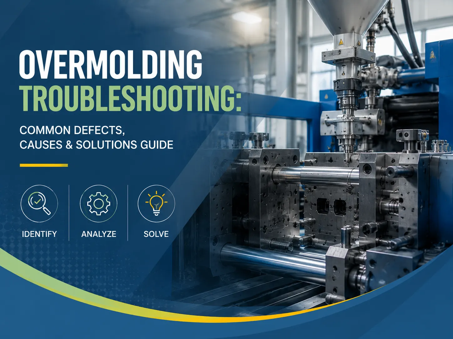
Overmolding Troubleshooting: Common Defects, Causes & Solutions Guide
You have started the overmolding process wherein applying a soft TPE grip on an ABS handle or even a silicone gasket over the PBT housing seems to go wrong straight away with the first product from the facility. Maybe it’s a situation when the overmold is popping off just like a sticker that comes off easily or maybe there is flashing present at the area where the component pieces are assembled. It is also possible that burn marks, sink marks, or ugly flow lines appear, but whatever the situation ends up being, it requires corrections in the process. Overmolding defects are among the most tedious issues of injection molding since it involves two materials, two shots, and a binding interface. The guide that is to be discussed below presents an opportunity to look through some common issues associated with overmolding, their nature, and the solutions as well. Whatever the problems might be from the mold temperature, and injection pressure to the compatibility of materials and placement of the gate, you can always solve them with this guide.
Quick answer: Overmolding defects are predominantly due to poor adhesion/delamination (attributable to contamination of substrate surface, outside of heating, and incompatible materials), flash (too much of clamp force losses and use of faulty tool), short shots (if injection pressure is low, melt of low temperatures has been used, or because of ventilation issues), burn marks (the reason is trapped air caused by improper venting), sink marks (the cause is excess wall thickness or insufficient packing pressure), warping (the sources include incomplete cooling or different shrinkage), as well as splay/silver streaks (water present in resin). To fix overmolding defects, professionals need to check if the material is suitable (grade of the TPE or TPU matches the material used), whether the substrate is preheated, and work on optimizing temperatures for melting and molds. It is noted that about 70% of the defects in overmolding can be controlled by temperature management and preparation of the surface, and all these issues should be solved before looking for more complicated reasons for the problem.
Understanding Overmolding: Process Overview & Why It Fails
Overmolding is a multi-step process of injection molding where two different materials (usually a soft elastomer such as TPE, Tpu and silicone) are placed on a hard base (such as ABS, PA, PC, PBT and metal). It allows creating a single piece with good durability and soft surface. This technique is widely applied in the production of tool grips, electronic containers, medical devices and consumer products.Benlong’s own work on MCB injection mold manufacture demonstrates the level of precision required in multi-material molding for electrical components.
There are two main methods:
| Method | How It Works | Common Failure Points |
|---|---|---|
| Insert molding | Rigid substrate is pre-molded, placed into a second tool, then overmold material is injected | Insert placement errors, temperature differential, poor surface prep |
| Two-shot (rotary) molding | Both materials molded in a single machine with a rotating mold | Misregistration, material bleed at interface, timing issues |
One of the main challenges encountered in over-molding is adhesive issues at the interface, either in the form of a chemical bond (molecular melt binding) or mechanical bond (locks in shape). Failure at the bond results in failure of the entire element. In fact, almost every problem regarding over-molding is reduced to a single question — whether the bond between the two materials in the interface occurred as planned.
Key Process Variables That Drive Defects
- Overmold material melt temperature – low temperatures = slow melt and weak bonds; high temperatures = degradation and film
- Mold temperature – dictates speed of cooling, crystallinity, and bond formation
- Injection speed and pressure – very fast speed could create flash and burns, very slow speed could lead to premature curing of plastics
- Packing pressure and time – not enough packing would result in low density and voids in the end product
- Preheated substrate temperature – an important element for chemical bonding; cold substrate creates thermal shocks
- Cooling time – if it is too short, it’s creating distortion and ejection marks, if it takes too long, it’s losing the purpose of operation altogether
- Venting – it’s the air that gets trapped that creates burn spots on the plastic and prevents it from becoming faulty
Poor Adhesion & Delamination — The #1 Overmolding Problem
If the overmold material comes off or breaks free from the substrate right after it has been molded or after some time of use, this is a sign of delamination or adhesion failure. This is a widely observed problem in the process of overmolding whereby around 40-50% of complaints on overmolding quality arise from it.
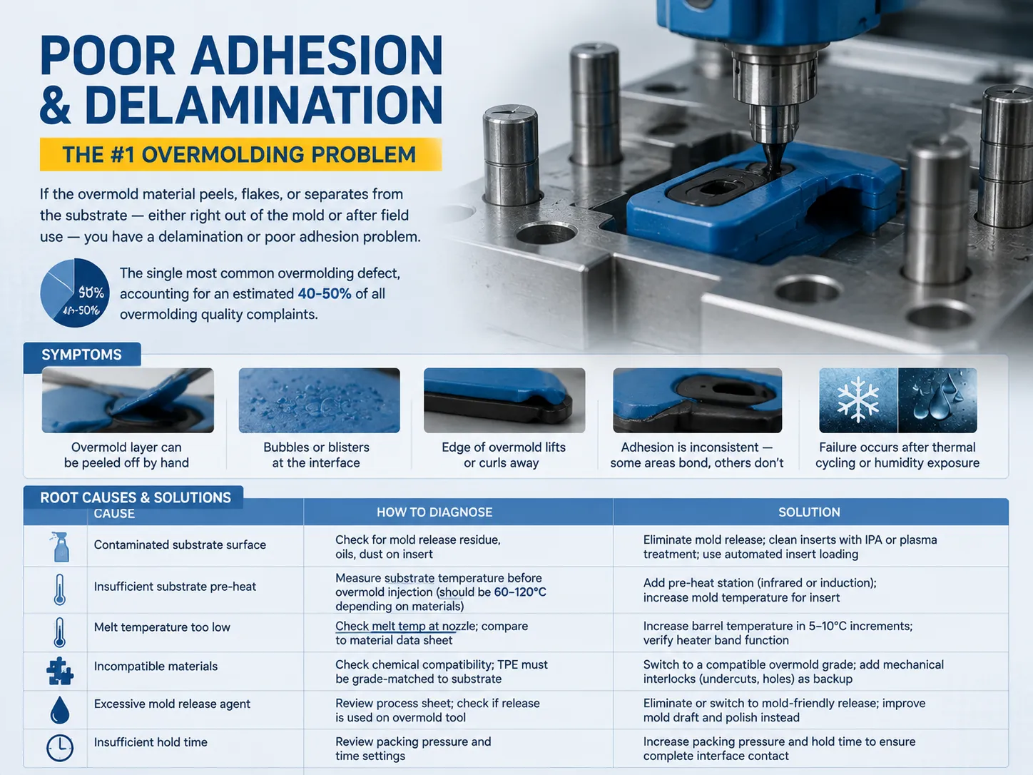
Symptoms
- Overmold layer can be removed by hand
- Bubbles or blisters are seen between the two layers
- The overmold shrinks or curls away from the base material
- Adhesion is varied; some regions bond while others do not
- Defect occurs after thermal cycling or moisture exposure
Root Causes & Solutions
| Cause | How to Diagnose | Solution |
|---|---|---|
| Contaminated substrate surface | Check for mold release residue, oils, dust on insert | Eliminate mold release; clean inserts with IPA or plasma treatment; use automated insert loading |
| Insufficient substrate pre-heat | Measure substrate temperature before overmold injection (should be 60–120°C depending on materials) | Add pre-heat station (infrared or induction); increase mold temperature for insert |
| Melt temperature too low | Check melt temp at nozzle; compare to material data sheet | Increase barrel temperature in 5–10°C increments; verify heater band function |
| Incompatible materials | Check chemical compatibility; TPE must be grade-matched to substrate | Switch to a compatible overmold grade; add mechanical interlocks (undercuts, holes) as backup |
| Excessive mold release agent | Review process sheet; check if release is used on overmold tool | Eliminate or switch to mold-friendly release; improve mold draft and polish instead |
| Insufficient hold time | Review packing pressure and time settings | Increase packing pressure and hold time to ensure complete interface contact |
Pro tip: The fastest way to diagnose adhesion problems is to conduct a crosshatch peel test. If the adhesion fails at the center but adheres at the sides, the issue is probably contamination or the temperature of the substrate. If the adhesion fails all over, the material is possibly incompatible.For a deeper dive into mold development precision, our guide on the MCB injection mold development process covers mold flow analysis and tooling tolerances that apply directly to overmolding tools.
Flash and Excess Material
Flash refers to the extra material that leaks out from the mold cavity along the separation line or through the spaces created by inserts or ejector pins. In the case of overmolding, this flash is particularly problematic as it can find itself wrapped around the substrate and forming undesired and troublesome edges.
Primary Causes
- Low clamping force — injection pressure greater than the clamping force
- Aged tools — parting line wear, ruined insert tools or enlarged ejector pin holes.
- High injection pressure or velocity — material goes through voids
- Mold temperature too hot — material is fluid, and goes through the void
- Too deep venting channels — created for air but material passes through.
Fixes
Boost the clamping force (if machine capacity allows), decrease the injection pressure throughout the pack stage, lower the melting temperature by approximately 5 to ten degrees Celsius, examine and repair the damaged parting lines, and confirm the depth of the vent (usually approximately 0.01-0.03 mm for the TPE). If there is still a flash at the insert side, check to make sure that the insert is correctly placed and that the insert locator is not worn out.
Short Shots and Incomplete Fill
A short shot happens when the overmolding material fails to completely fill the mold cavity, resulting in parts that are not fully formed. This is often one of the first defects you will see during the commencement of the process.
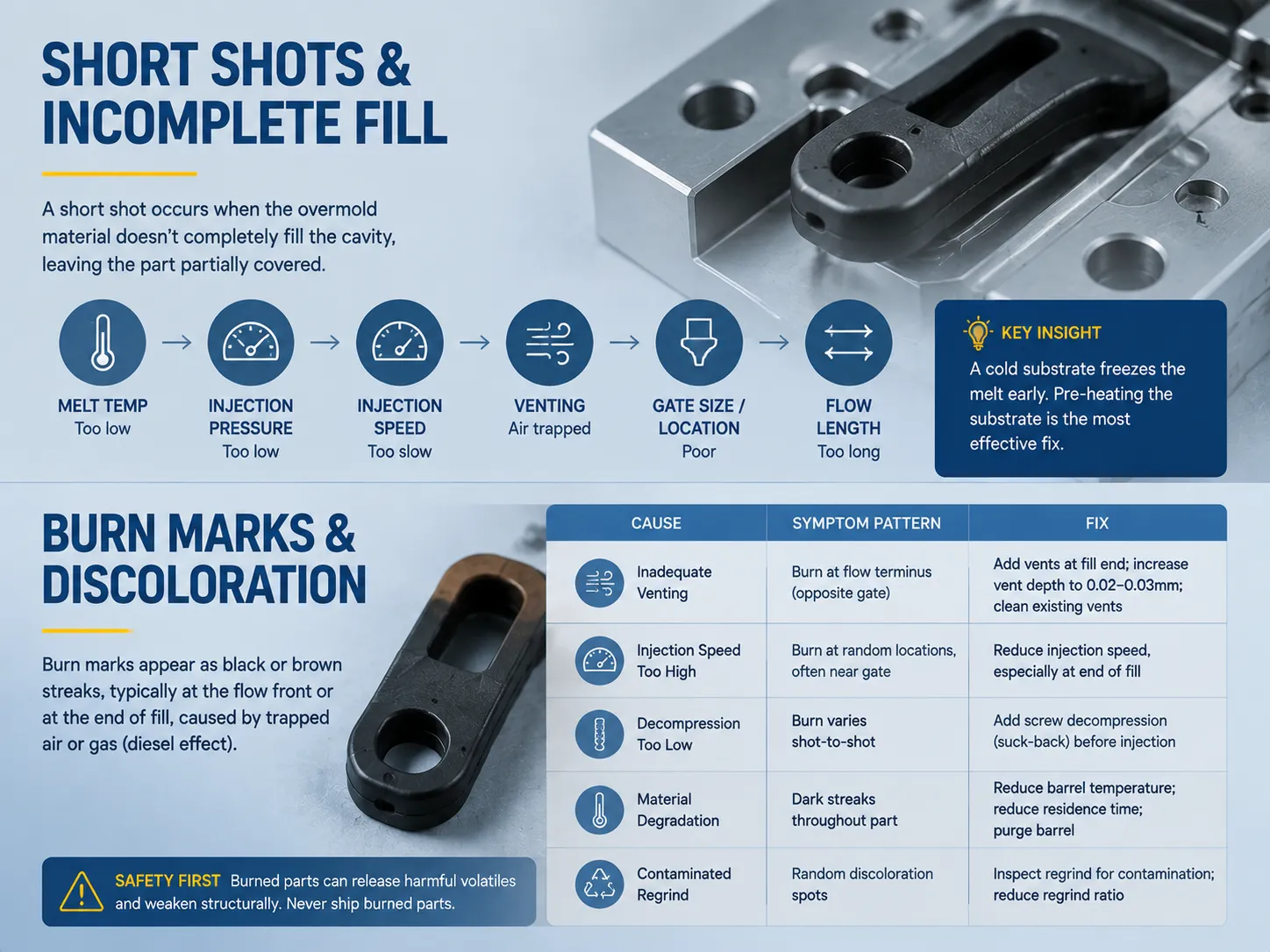
Quick Diagnostic Flow
| Check | If Problem | Action |
|---|---|---|
| Melt temperature | Below recommended range | Increase barrel temp; check for burned-out heater bands |
| Injection pressure | Below fill requirement | Increase pressure; verify screw forward time |
| Injection speed | Too slow — material freezes before fill | Increase speed; profile injection (fast-slow-fast) |
| Venting | Air trapped in flow path end | Add or clean vents at flow terminus; check vent depth |
| Gate size/location | Gate too small or poorly placed | Enlarge gate; relocate gate closer to thick sections |
| Flow length | Exceeds material’s L/T ratio | Change to higher-flow-grade material or add flow leader |
Main point to consider: In the process of overmolding, short shots can occur, and this is due to the substrate that acts as a heat sink. Being cold, the substrate turns the overmold material into solid in the area of contact. Pre-heating the substrate is one of the most effective solutions to the problem — sometimes an increase of substrate temperature by only 40°C helps improve flow efficiency remarkably.
Burn Marks and Discoloration
Burn marks manifest as streaks, usually black or brown, found at either the flow front or end of the fill. It is a phenomenon occurring due to the compression of trapped air or gas by the hot melt — also referred to as the “diesel effect.”
Causes & Solutions
| Cause | Symptom Pattern | Fix |
|---|---|---|
| Inadequate venting | Burn at flow terminus (opposite gate) | Add vents at fill end; increase vent depth to 0.02–0.03mm; clean existing vents |
| Injection speed too high | Burn at random locations, often near gate | Reduce injection speed, especially at end of fill |
| Decompression too low | Burn varies shot-to-shot | Add screw decompression (suck-back) before injection |
| Material degradation | Dark streaks throughout part | Reduce barrel temperature; reduce residence time; purge barrel |
| Contaminated regrind | Random discoloration spots | Inspect regrind for contamination; reduce regrind ratio |
Burn marks are a concern for safety because of the inability of old parts to perform their given functions due to the weakening of structures and the release of harmful chemicals. Never ship a burned part. When only making modifications to the venting of the part does not work, consider changing the design and to direct the airflow to the current vents.
Sink Marks and Surface Depressions
Sink marks are shallow depressions on the surface of the overmold, typically appearing over thick sections, ribs, or boss locations where material shrinks unevenly during cooling.
What Causes Sinks
- Wall thickness too much – thick areas cool more quickly than thin sections.
- Low packing pressure – the material is not squeezed enough prior to solidification.
- Packing time not sufficient – the neck freezes before filling is over.
- Mold temperature is too high – of long cooling time allows for shrinkage.
- Rib or boss thickness too large – the rib thickness must be ≤60% of the wall thickness.
Practical Fixes (Priority Order)
- Raise packing pressure – this is the first solution we recommend for most sink types. Increase gradually by 10 bar increments until the sink disappears, or the flash appears.
- Increase packing time – continue keeping pressure until the gate freezes. In order to find the
- weight at which the gate freezes, perform the weighing procedure at various hold times.
- Decrease wall thickness – if possible, remove parts of the wall at the design stage.
- Lower temperature of the mold – quicker cooling means less shrinkage.
Warpage and Dimensional Distortion
Warpage happens when different sections of the part cool down at different speeds, which leads to the twisting, bending, or cupping of the finished part. This problem gets even worse with overmolding due to different coefficients of thermal expansion (CTE) of the two materials used which are cooling down at the same time.
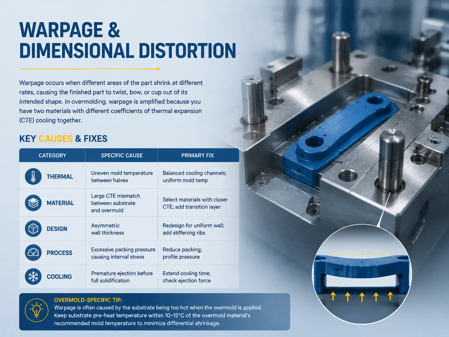
Key Causes
| Category | Specific Cause | Primary Fix |
|---|---|---|
| Thermal | Uneven mold temperature between halves | Balanced cooling channels; uniform mold temp |
| Material | Large CTE mismatch between substrate and overmold | Select materials with closer CTE; add transition layer |
| Design | Asymmetric wall thickness | Redesign for uniform wall; add stiffening ribs |
| Process | Excessive packing pressure causing internal stress | Reduce packing; profile pressure |
| Cooling | Premature ejection before full solidification | Extend cooling time; check ejection force |
Tip related to overmolding: Warpage typically occurs due to excessive heating of the substrate during overmolding. The substrate expands/ shrinks due to thermal effects, which causes connection with overmold in the state of the substrate being expanded.After being cooled, the substrate shrinks significantly more than expected. Keep pre-heating temperature of the substrate within 10°–15°C of the mold temperature recommended for the overmold material so that differential shrinkage is kept to a minimum.
Splay Marks, Silver Streaks & Moisture
Splay marks, commonly classified as silver streaks, are characterized by the pattern of fan-shaped or streaky shapes on part surfaces. These marks are typically initiated in the gate and expand outward. In general, the formation of splay marks is a result of moisture getting converted to steam in the resin during the process of injection.
Moisture Is the Usual Suspect
Both TPE and TPU plastics are hygroscopic. TPU, in particular, tends to absorb moisture quickly, so it should be dried properly. Check the following:
- Drying time and temperature — TPU usually requires 2 to 4 hours of drying at a temperature between 80 and 110°C; TPE typically requires 2 to 3 hours of drying at a temperature between 70 and 90°C.
- Dryer function — check the dewpoint temperature (it must be below -30°C) and also verify the condition of the desiccant material.
- Material residence time in a hopper — if materials are left in an open hopper for too long, they can re-absorb moisture.
- Efficiency of the vents — humidity that is trapped in the mold is converted into splay defects.
Other Causes of Splay
- Air is entrained – screw speed is too high during the process of recovery and air gets pulled into the melt.
- The decompression is too high as there is too much of a suck-back effect.
- The material is contaminated – resins are mixed and have different melting points.
- The nozzle drools – the material is coming out of the nozzle in strings and creates pockets of air.
Quick tip: Understand that if splay starts suddenly during or after a material change or because of a weekend shutdown, it can be solved by purging the barrel well by using 3-5 shots of virgin resin and checking the dryer.For more on maintaining production line quality and minimizing downtime, see our guide on manufacturing plant shutdown checklists.
Flow Lines and Weld Lines
Flow lines are patterns seen on the part exterior that indicate the direction of the molten material. Weld lines show the point at which two flow streams converged and joined. These two features can be seen in overmolding due to the complicated geometric structure of the substrate.
Distinguishing the Two
| Feature | Flow Lines | Weld Lines |
|---|---|---|
| Appearance | Wavy streaks following flow direction | Visible seam where flow fronts merge |
| Location | Anywhere between gate and fill end | Behind holes, pins, or split flow paths |
| Structural concern | Usually cosmetic only | Can be a weak point — always test strength |
| Primary cause | Melt temperature too low or speed too slow | Flow fronts meet too cold to fully fuse |
Fixes for Flow Lines
- Raise the melting point by 5 to 10 °C.
- Increase the speed of injection (especially at the beginning).
- Take the temperature of the mold up to make the cooling process slower.
- Make the gate larger or put it nearer to the problem area.
- Use material of a higher flow grade.
Fixes for Weld Lines
- Raise the temperatures for the melting process and the mold so that the flow fronts arrive at the weld joint at a higher temperature
- Increase the resin injection speed to shorten the time between the point of flow split and that point of rejoin
- Add an overflow well at the location of the weld joint to eliminate cold material
- Move the gate to a less sensitive location for the joining of the flow fronts
- If the weld line is structural in nature, there can be a mechanical interlock feature provided in the weld area as a precaution feature
Color Contamination and Streaking
Color streaks or unexpected color variations in the overmold are usually caused by residual material from a previous run, contaminated regrind, or color concentrate issues.
Common Scenarios
- The dark color that precedes any lighter shades creates streaks when colors are transferred. A 20 to 30 shot purge of the barrel is necessary or the use of a purge compound can be performed.
- The contamination caused by various colors can also result in this streaking effect. However, segregation based on color and material is necessary.
- If there are color concentrate problems, by increasing the of RPM of the screw during plastication and increasing the backpressure, the problem can be solved.
- There is a possibility of nozzle wear since in this case material tends to get stuck before releasing.
- Clean the hopper thoroughly after changing material.
- Make sure to have the proper purge procedures in place during overmolding since this is true in cases where multiple formulations are used in production.
Master Troubleshooting Checklist
When a new defect is detected in the overmolding line operations, follow the checklist sequentially. The checklist helps to solve 80% of the problems with simple process or material causes before the introduction of any tool modification.

| Step | Check | What to Look For |
|---|---|---|
| 1 | Material verification | Correct material grade? Correct drying time/temp? Moisture content ≤0.05% for TPU? |
| 2 | Melt temperature | Within data sheet range? Measured at nozzle with pyrometer? |
| 3 | Mold temperature | Within range? Both halves balanced? Cooling flow verified? |
| 4 | Substrate pre-heat | Temperature measured on insert before placement? Consistent? |
| 5 | Injection profile | Speed profile appropriate? Pressure sufficient for fill? |
| 6 | Packing pressure & time | Sufficient to prevent sink? Long enough for gate freeze? |
| 7 | Clamp force | Sufficient to prevent flash? Machine capacity matched to projected area? |
| 8 | Venting | Vents clean? Correct depth (0.01–0.03mm)? Vents at flow terminus? |
| 9 | Tool condition | Parting line sealed? Ejector pins not worn? Gate not worn? |
| 10 | Cycle consistency | Cycle time stable? Shot weight consistent? No hesitation or variation? |
The most common guideline is to change one variable at a time and wait 10-15 trials to ensure that the situation is stable before evaluation the effect. Many times the solutions fail to appear working just because there was not enough time for the change to take place fully. For detailed guidance on selecting and maintaining injection molding equipment, our reference on MCB injection mold products provides specifications relevant to precision molding operations.
Frequently Asked Questions
What is the most common overmolding defect?
The uncomplicated overmolding defect that happens due to a bad bond between layers is the most frequent defect found in overmolding, making about 40-50% of all defects. The causes of this condition are usually contaminated surface of the substrate, lack of substrate pre-heating, low temperature of the melting material, or combination of different materials. The quickest way to identify these defects is to check the substrate temperature before injecting, as well as to perform a peel test. To solve the issue, firstly deal with contamination, and then change the temperatures of the process.
Why is my overmold peeling off the substrate?
Peeling is a sign of a failure in adhesion at the interface of materials. The top three causes are 1) mold release residue on the substrate – remove the release agents or choose alternatives that are compatible with the mold; 2) substrate being too cold – the overmolding getting frozen upon contact; thus, preheat the substrate between 60 and 120°C; 3) materials not compatible, i.e., the TPE grade might not be chemically compatible with the substrate resin. Check compatibility charts of the supplier materials and select the right grade of the overmold.
How do I prevent flash in overmolding?
There are three elements that need to be observed for the purpose of flash prevention: 1) proper clamping force to be exerted (i.e. to ensure that projected area x injection pressure does not exceed the capacity of clamping; 2) worn tooling (check parting lines and refurbish them as needed); 3) process parameters (melt temperature and injection speed should be lower due to the effects of the pack phase). If flash is observed along inserts, then checks should be made regarding insert seating.
Can I overmold without pre-heating the substrate?
It is possible to skip that operation, but the adhesiveness may be inconsistant and substandard. Preheating the substrate allows the temperature of the substrate to be brought closer to the melting temperature of the molding plastic and thus undergo sufficient degree of molecular diffusion at the interface. When molding TPE over ABS the optimum temperature range of the substrate is between 80°C and 100°C. Although omitting preheating may seem to shorten the cycle time, the increase in the waste and returns due to delamination will make this decision completely pointless.
References
- Society of Plastics Engineers (SPE) — Overmolding & Multi-Component Molding Technical Resources
- SPE — Injection Molding Division Process Guides
- NPE — The Plastics Show, Overmolding Technology Presentations
- Injection Molding Magazine — Troubleshooting Articles
- KraussMaffei — Multi-Component Injection Molding Technical Guides
- ENGEL — Overmolding Process Technology Documentation
- Plastics Technology — Overmolding Defect Analysis & Solutions
- ASTM International — Standard Test Methods for Plastic Materials and Molding
The procedure for fixing problems with overmolding doesn’t have to be based on guesswork. Most defects such as poor adhesion, flash, short shots, burn marks, sink marks, warpage, splay, and contamination can be attributed to one or more of the following causes: temperature control, both at the melt and mold stage, as well as at the substrate stage; material compatibility and drying; pressure and speed profiles; tool condition. You just need to work through the checklist in this guide and change the parameters one at a time to arrive at a solution in just a few minutes instead of several days.
The most important principle to remember is to first fix the temperature and surface preparation. About 70% of all defects associated with overmolding stem from thermal mismatch or contamination at the bonding site. In other words, if a substrate is clean, pre-heated, and melt temperature is within specification, then most causes of defects are eliminated before they can lead to costly causing of scrap.