benlong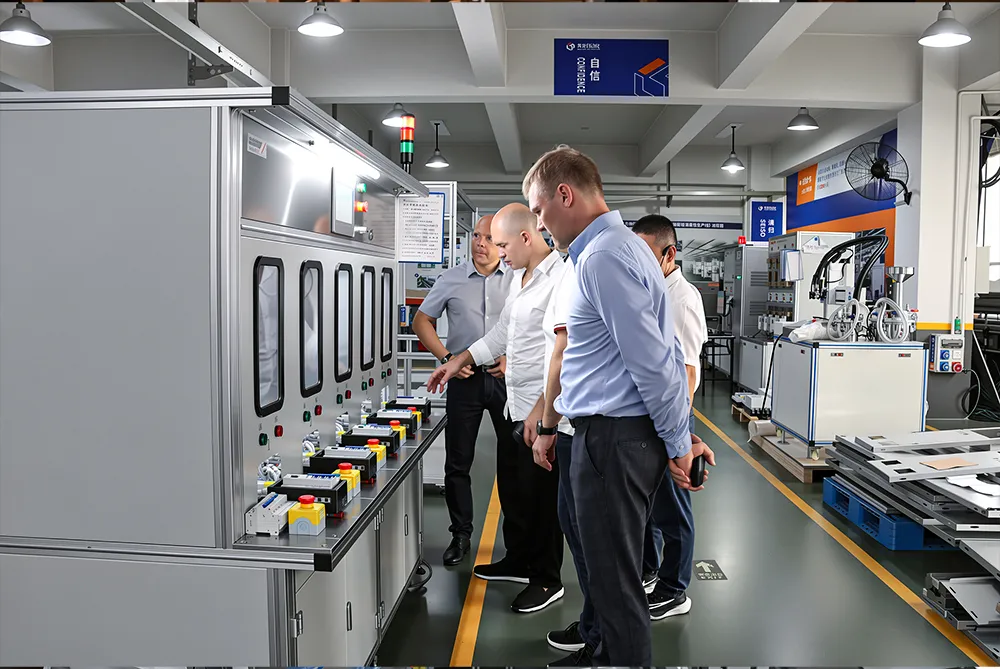


Electric Meter Test Equipment: Complete Guide to Calibration Benches and Accuracy Verification
Release Time: 2026-09-04
Precise energy measurement is crucial for the electricity billing system, grid operations, and compliance with the correct standards. Whether it is utility laboratories, meter devices manufacturing plants or independent calibration services, it is safe to say that all electrical current measurements will be reliable and accurate as long as thorough testing procedures are followed. Obtaining inaccurate readings would lead to revenue losses, client’s lawsuits, or violation of the requirements posed by international standard IEC 62053. This article will provide comprehensive information about the principles, standards, techniques, and best practices of proving electric meter measurement accuracy, including high-precision manual calibration benches for single-phase and three-phase meters.
The modern electric meter testing procedures include not only basic testing but also harmonic tests and creeping tests and imply the usage of automated software sequence, reference standards (0.05% accurate) and stable power supply sources. The knowledge of these components allows companies to choose the best solution for electric meter quality control or for testing purposes.
What is Electric Meter Testing?
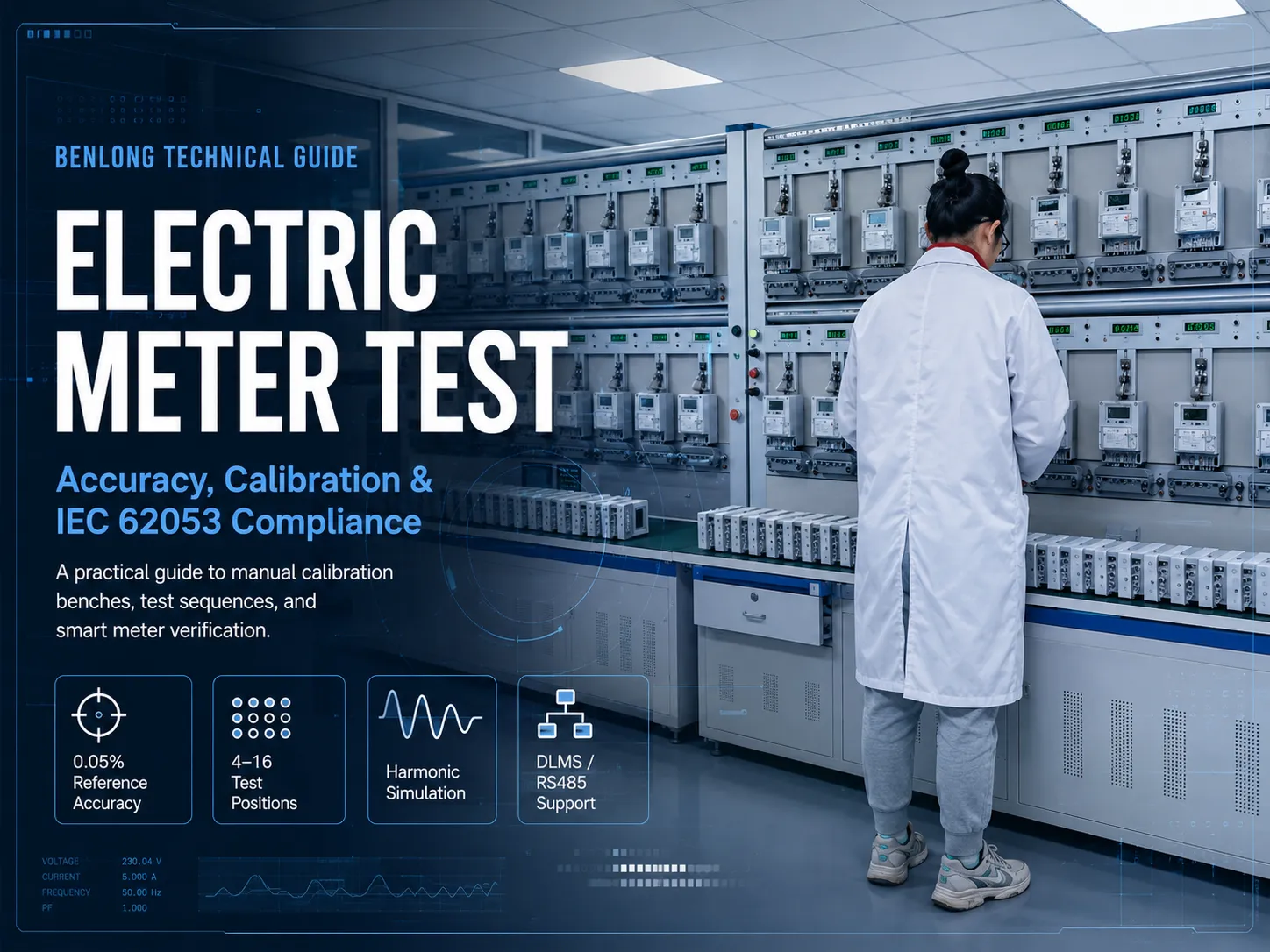
Electric meter testing means a systematic verification process done to confirm energy meters accuracy, functionality, and parameters’ correctness under the specified conditions, in other words, to check that the electric meter provides correct readings of active and reactive energy up to the error limits allowed by the corresponding accuracy class (0.2, 0.5, 1, or 2) according to IEC 62053-11/22/23 national equivalence.
Among standard electric meter testing procedures can be distinguished:
– Basic error test means checking percentage error of active and reactive energy readings;
– Starting test is determining the minimum current after which the meter provides some readings;
– Creeping test is checking that the registration of energy readings is performed under idle conditions;
– Harmonic test is proving if the meter provides the correct readings of energy under various voltage/current waveforms in particular harmonic conditions;
– Influence quantity testing means measuring the impact of voltage, frequency, temperature, etc.
– Testing the maximum load and timing error for smart energy meters.
– Checking the communication protocol (optical communication port, RS485, DLMS/COSEM, Modbus).
Why Electric Meter Test Accuracy Matters
Energy meters are the cash registers of the electricity industry. Even a small systematic error of 0.5% across millions of meters can result in significant financial discrepancies. Regulatory bodies and utility commissions therefore mandate periodic electric meter test and calibration. Manufacturers must also perform 100% or statistical sampling tests before shipment to guarantee product quality.
Key reasons for rigorous electric meter test programs include:
- Revenue protection – preventing under- or over-billing.
- Regulatory compliance – meeting IEC, ANSI, or local metrology requirements.
- Customer confidence – reducing billing complaints and legal disputes.
- Grid data quality – accurate meters support load forecasting, demand response, and smart-grid analytics.
- Long-term reliability – early detection of component drift or design weaknesses.
High-quality electric meter test equipment with traceable reference standards (Class 0.05%) provides the measurement certainty needed to certify meters of Class 0.2 and lower accuracy.
Types of Electric Meter Test Equipment
Several categories of equipment are used for electric meter test activities, ranging from portable field testers to fully automated production lines. The most versatile and widely used solution in laboratories and mid-volume manufacturing is the manual (or semi-automatic) calibration bench.
Portable Field Testers
Compact single-phase or three-phase instruments used by utility technicians for on-site verification. They typically offer lower accuracy (0.1%–0.5%) and limited load ranges compared with laboratory benches.
Manual Calibration Benches
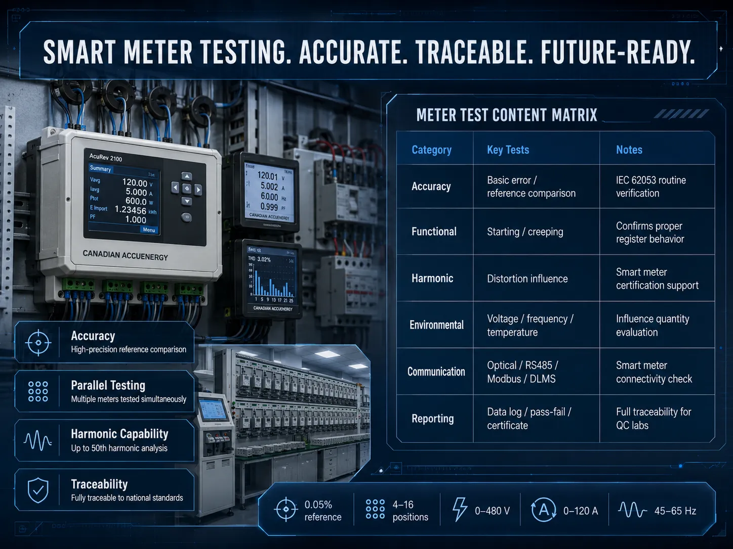
These systems allow operators to load and unload meters by hand while the test sequences themselves are fully automated. They are ideal for mixed-model production, type testing, and calibration laboratories where flexibility is more important than maximum throughput. A typical three-phase manual calibration bench supports 4 to 16 positions, voltage up to 480 V, current up to 120 A, and reference accuracy of 0.05%.
Fully Automatic Test Lines
Integrated production systems that combine conveyor transport, robotic handling, calibration, aging, and communication testing. Suitable for high-volume smart-meter factories producing tens of thousands of units per day.
Aging and Long-Term Stability Benches
Used to apply continuous voltage and current for extended periods (hours to days) while monitoring register accumulation, communication stability, and thermal performance.
For most utility labs and specialized manufacturers, a custom multi-position manual electric meter test bench offers the best balance of accuracy, flexibility, and cost.
Key Components of a Modern Electric Meter Calibration Bench
A professional electric meter test system consists of several integrated subsystems:
- The programmable power source produces a stable three-phase current and voltage ranging from 0 to 480 volts and 0 to 120 A amps, respectively, with a gross distortion (THD) of less than 0.5%. The frequency is able to be adjusted from 45 Hz to 65 Hz.
The reference standard includes a precise Class 0.05% power meter making known measurements and ensuring the accuracy of measurements in compliance with requirements of national metrology institutions.
The multi-position test rack allows for simultaneous work with 4 to 16 measuring devices. The devices can accept different connection types such as sockets, terminals, or rails.
A harmonics generator can produce up to the 21st harmonics of both voltage and current of variable amplitude and phase.
The communication ports of the system include optical heads, RS485 communication ports, as well as wireless modems allowing the use of different communication protocols.
The software of the system is responsible for formation of test commands, comparison with reference values, evaluation of measurement accuracy, data logging, and generation of calibration certificates.
Safety and emergency stop systems will ensure the safety of personnel and proper equipment operation.
Cooperation of each system leads to automation of the measurement process and accomplishment of the entire measurement cycle with minimal operator involvement after the loading stage.
Standard Test Sequences in Electric Meter Calibration
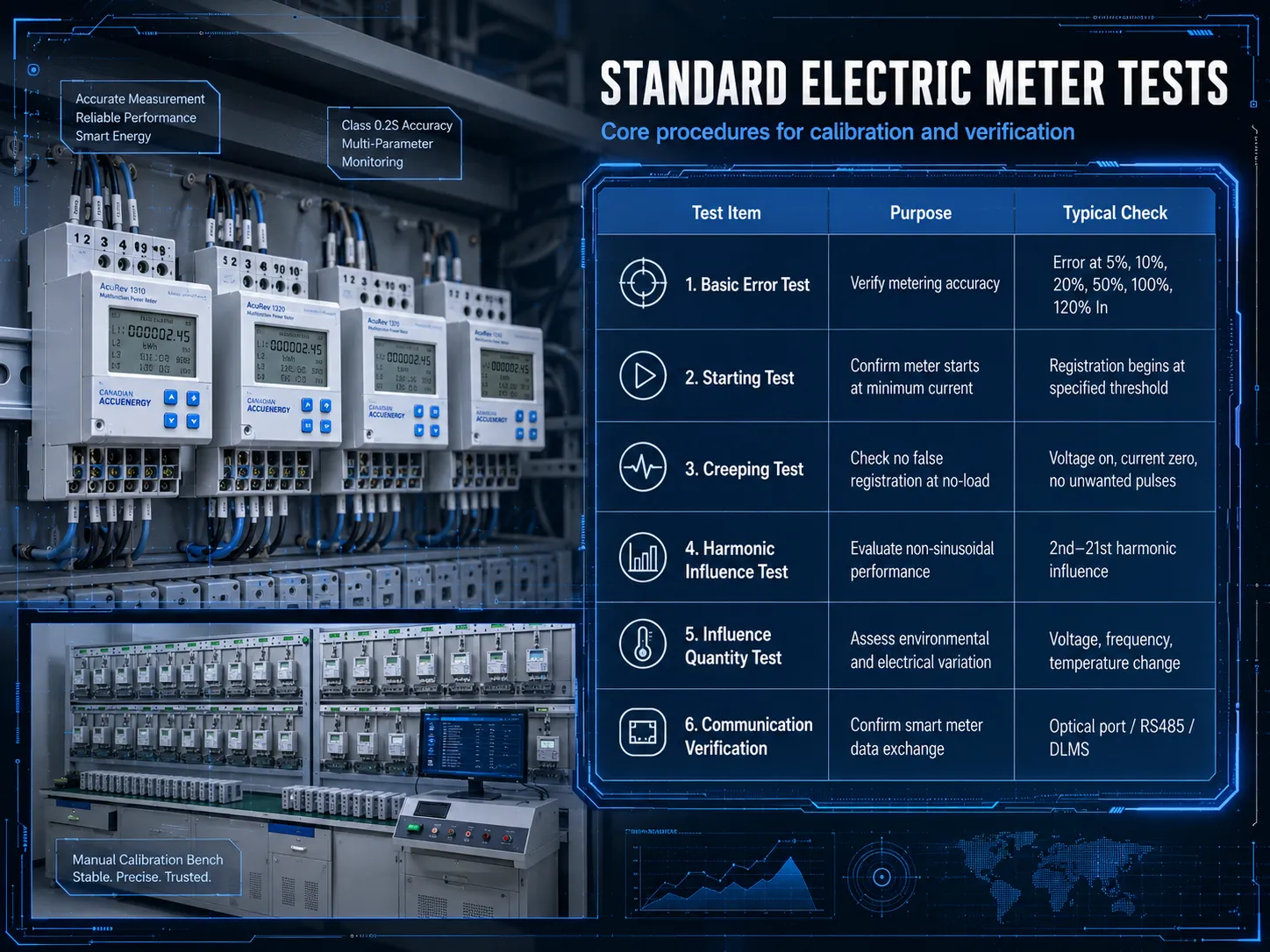
In a normal automated procedure on a manual calibration bench, we can see the following steps according to the world standards:
Visual and connection verification – to make sure that the correct type of meter is used in the system.
Starting current test – to apply the lowest amount of current that is requested for the meter class for appearance of the measurement.
Basic error test – to make an estimation of the percentage of error for different load conditions in the system (at 5, 10, 20, 50, 100 and 120% of rated current) and with different powers factors (1, 0.5 inductive, 0.8 capacitive).
Creeping test – to apply rated voltage with fully zero current and rats confirm that there is no pulse output or register movement over the agreed limit.
Harmonic influence test – to inject harmonics and therefore measure extra errors that were created.
Influencing parameters tests – to change the voltage, frequency or temperature.
Communication and registers confirmation – to read energy registers and maximum demand through optical or RS485 connection and compare them with reference index.
Data logging and certificate generation – to keep all measuring results and data with proper id, date and name of the person working processes.
Technical Specifications of High-Precision Calibration Benches
When selecting electric meter test equipment, the following specifications are critical:
| Parameter | Typical Specification |
|---|---|
| Meter compatibility | Single-phase or three-phase, active/reactive, Class 0.2/0.5/1/2, direct or CT connected |
| Number of test positions | 4 / 8 / 12 / 16 (customizable and expandable) |
| Voltage range | 0 – 480 V (three-phase), accuracy ±0.05% |
| Current range | 0 – 120 A per phase, accuracy ±0.05%, THD < 0.5% |
| Frequency range | 45 – 65 Hz, accuracy ±0.01 Hz |
| Reference accuracy | 0.05% (Class 0.05S) |
| Harmonic simulation | 2nd to 21st order, programmable amplitude and phase |
| Communication | Optical port, RS485 (Modbus, DLMS/COSEM), pulse output |
| Power supply | 380 V ±10%, 50 Hz, three-phase four-wire |
Custom designs can extend voltage or current ranges, add temperature chambers, or support additional protocols according to specific customer requirements.
Applications of Electric Meter Test Systems
Electirc meter test equipment serves several industries.
Quality control of meter manufacturing: 100% testing of meters prior to shipment and packing, or statistical sampling to confirm quality of every batch.
Measurement laboratories: testing of new and refurbished meters and control of approval measurement tests.
Independent calibration service providers: specialized laboratories operating under accreditation and issuing certificates of traceable calibration.
Research and development: measuring new meter prototypes’ performance under various conditions of harmonic distortion, temperature and ambient effects.
Incoming inspection: utilities performing meter inspection upon receipt from suppliers.
In all of the above cases, the laboratory throughput and economical efficiency are significantly increased by testing many meters at the same time and with high accuracy.
Standards and Regulatory Requirements
The primary international standards governing electric meter test procedures are:
- IEC 62053-11 – Particular requirements for electromechanical meters.
- IEC 62053-22 – Particular requirements for static meters for active energy (Classes 0.2S and 0.5S).
- IEC 62053-23 – Particular requirements for static meters for reactive energy.
- IEC 62052-11 – General requirements, tests and test conditions.
- National standards derived from the IEC series or ANSI C12 series in North America.
Calibration benches must themselves be traceable and periodically verified against higher-level standards to maintain measurement validity.
How to Choose the Right Electric Meter Test Bench
In order to choose appropriate electric meter test equipment certain factors should be taken into account:
①.Accuracy class of the meters to be tested – a reference standard at least five times more accurate than the devices under test should be selected (typically 0.05% for Class 0.2 meters).
②.Number of positions and throughput requirements – 4 to 8 positions are appropriate for laboratories while production use requires at least 12 to 16.
③.Meter form factors – make sure that the supplier can design custom adapters for the meter types (like socket, terminal-block, or DIN-rail meters).
④.Communication needs – confirm that the equipment supports the communication protocols that are compatible with the meters used.
Harmonic and influence testing capabilities – necessary for smart-meter certification.
⑤.Software and data management – the equipment should provide sequence editors, automatic report generation, and MES/ERP communication capabilities.
⑥.Experience and support of the supplier – choose manufacturers with a good reputation that can provide expert knowledge and offer high-standard after-sales services.
A good choice of a test bench allows it to serve for over 10 years.
Advantages of Custom Manual Calibration Benches
Compared with off-the-shelf systems, custom-designed electric meter test benches offer clear benefits:
- Perfect mechanical and electrical match to the customer’s specific meter models.
- Ability to mix single-phase and three-phase positions on the same rack.
- Modular expansion – start with fewer positions and add more later.
- Optimized test sequences that minimize overall cycle time.
- Full documentation and training tailored to the user’s operating procedures.
These advantages translate into higher testing efficiency, lower error rates, and faster return on investment.
Installation, Commissioning, and Training
A typical project timeline for a custom electric meter test bench includes:
- Requirement analysis and sample evaluation (10–15 days).
- Mechanical and electrical design of adapters and wiring (30–45 days).
- Manufacturing and internal testing (45–60 days).
- Factory acceptance test (FAT) with customer meters.
- On-site installation, commissioning, and operator training (5–7 days).
- Site acceptance test (SAT) and final documentation.
Professional suppliers provide comprehensive manuals, software licenses, calibration certificates, and remote support after handover.
Frequently Asked Questions
What accuracy class is required for the reference standard?
For testing Class 0.2 or 0.5 meters, a Class 0.05% (0.05S) reference is recommended to maintain an adequate accuracy ratio.
Can one bench test both single-phase and three-phase meters?
Yes. With interchangeable wiring adapters and software profiles, the same multi-position bench can handle both types, sometimes even in mixed batches.
How many harmonic orders are typically needed?
Most smart-meter standards require testing up to the 21st harmonic. A good bench should generate programmable harmonics from the 2nd to at least the 21st order.
Is DLMS/COSEM optical communication supported?
Modern calibration benches include adjustable optical heads and software drivers for DLMS/COSEM, IEC 62056-21, and other common protocols.
Can the number of test positions be increased later?
Many designs are modular. Additional four-position extensions can often be added, and the control software automatically recognizes the expanded configuration.
What is the typical lead time for a custom bench?
Standard configurations ship in 45–60 days. Fully customized systems usually require 90–120 days from order confirmation to delivery.
Conclusion
The importance of electric meter test methods cannot be overstated when it comes to accurately performing energy reading, proper bill charging and adhering to regulations. Special measuring devices incorporating references with an accuracy of 0.05%, simultaneous multi-channel testing, harmonic generation capabilities and ability to communicate with several protocols give laboratories and manufacturers the opportunity to have highly efficient and cost-effective technology at their disposal. Using equipment, meeting the specific case, accuracy class and communication requirements of the meters can significantly enhance performance of the organization in terms of productivity, traceability and stability in measuring results.
A wise investment in reliable and advanced electric meter test equipment guarantees good results in connection with producing a quality product and minimizing disputes. Whether you’re launching a new lab for testing electric meters or upgrading the existing facility, consulting firms offering electric meter calibration devices for meeting IEC 62053 standards and the peculiar needs of your business is advisable.