benlong


Automatic Screw Machine for MCCB Assembly: Terminal Torque Standards and a Reference Table
An automatic screw machine is well-suited for use in a molded case circuit breaker production line because of one crucial reason: the terminal screw is a vital safety joint, and torque is the only factor that guarantees its reliability. The terminal screw in an MCCB does not simply keep the wire in its place, but it also provides the mechanical clamping force which presses the conductor against the terminal. The clamping force itself dictates the contact resistance, current-carrying ability, and durability of the joint against vibration and heating over the years. The wrong torque will result in the failure of the joint, first quietly, then destructively.
The present article is intended for engineers who understand the importance of doing it properly. The article describes what the terminal MCCB screw does, the different torque regulations, and a reference chart with all the published torque figures.
What the MCCB terminal screw actually does
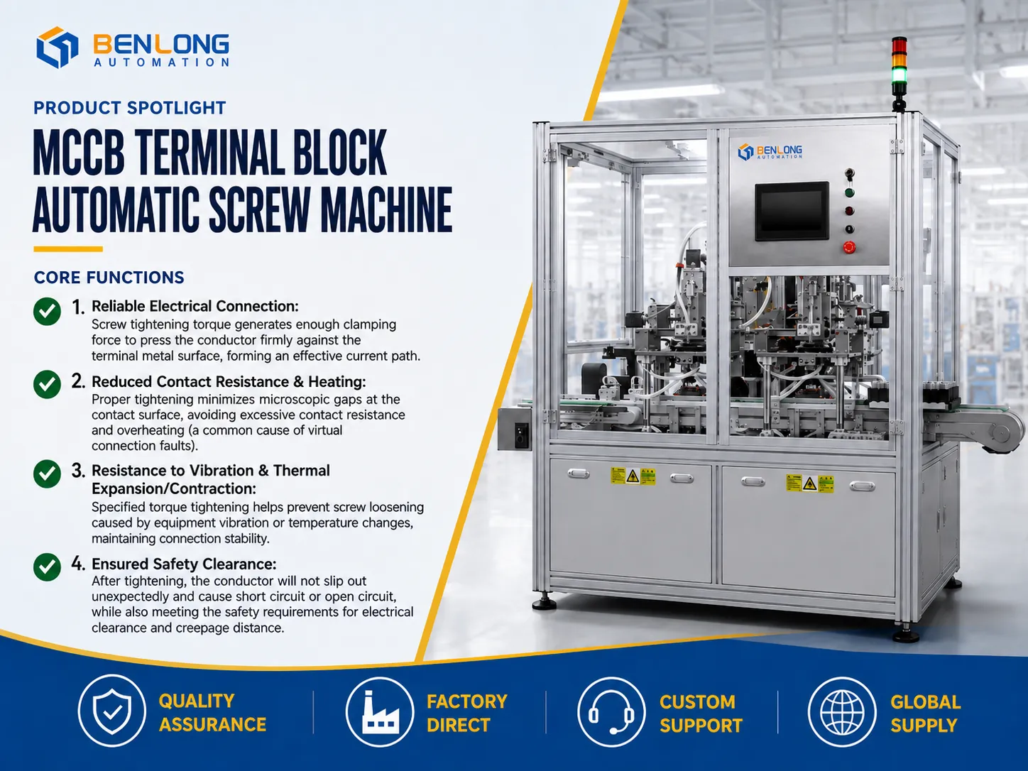
The key role of tightening an MCCB terminal screw is to secure the conductor firmly onto the current-conducting terminal by means of mechanical pressure resulting in the low contact resistance of the connection, its ability to carry the rated current and its resistance to loosening during the entire service life. It provides the following four requirements, each one being a case for the wrong torque leading to failure in the field.
Securing a reliable electrical joint. The screw’s torque provides the clamping force that brings the conductor into close contact with the terminal metal creating an efficient and low impedance circuit. An insufficient torque leaves a high-resistance junction already at the beginning of the operation.
Keeping contact resistance and temperature rise down. As the clamping is sufficient, the microscopic gaps at the junction get closed. High contact resistance leads to I²R heating and a loose or partial connection is usually one of the very common sources of ignition in a distribution board. That is the type of failure that torque control was designed to prevent.
Withstanding vibration and thermal expansion. A joint that is tightened with the right torque is able to resist self-loosening resulting from equipment vibration and the cyclic expansion and contraction of the copper during its operation. The right torque ensures a reliable connection throughout thousands of thermal cycles.
Ensuring safety of isolation. A properly tightened conductor will not work loose and create either a short or an open circuit, while the fitted assembly will continue to be compliant with the clearance and creepage requirements to which the breaker has been tested.
Both under-torquing and over-torquing are equally dangerous. An under-torqued screw leaves a loose, overheating connection, while an over-torqued screw can strip the thread, or the clamping can be damaged or the moulding cracked resulting in the joint showing a good joint in the workshop but failing in operation after a couple of cycles. It should be noted that a safe zone is a certain value but not a direction which is precisely why it is a risk to rely on manual guessing when large volumes are being manufactured.
The standards behind MCCB terminal torque
MCCBs are basically the IEC 60947-2 standards dealing with low-voltage circuit-breakers, with the basic rules sourced from IEC 60947-1. The requirement for terminals in this situation is absolute: those terminals must meet restrictions in terms of mechanical and electrical reliability and must be tightened using torque according to the table #4 of IEC 60947-1 that is based on the specific thread dimensions. Specifically, the torque of the terminal is a declared characteristic that is strictly associated with the type of screw thread used and validated during the tests.
Based on the fact that the right value is device specific, manufacturers publish them. In the case of some MCCB brands, the values are noted in the laser way on the terminals. As for the reputable brands, they include the values in terms of installation and terminals data sheets. Thus, the general recommendation for technicians can be formulated in an uncomplicated manner: the official torque for every device is the value written on the device in question as it keeps changing depending on the type of terminal and wire’s cross-section, conductor material and etc. The table below is merely a reference for some purpose.
It is necessary to be clear about what the actual tests pass the connections through because it helps to understand that the prescribed torque is non-negotiable. The verification process is described in the treaty that describes the verification process. During the torque verification process the wires are ginagamit in a specified manner to make sure that the connection does not get burnt and does not loose. The terminal that would stand only on the basis of lucky situations would never meet the requirement of this verification process.
MCCB terminal torque reference table
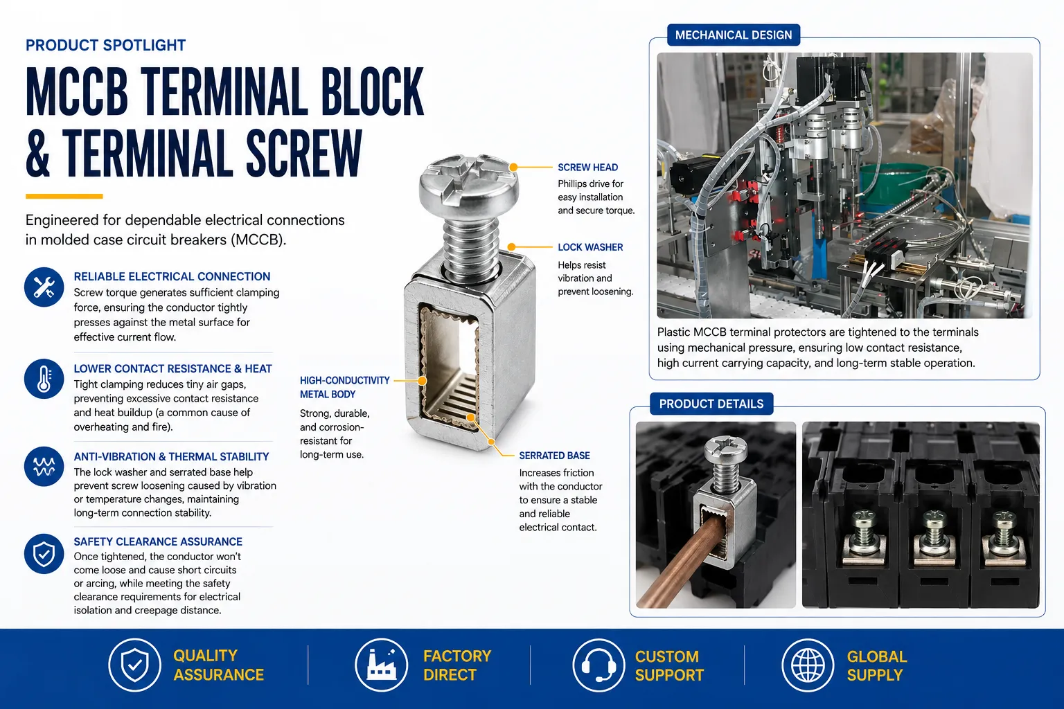
The table presents the published connection torques for two commonly used types of MCCB: ABB Tmax and Siemens 3VA, giving an overview of the values and allowing you to look up a value for a specific series/frame. The figures are extracted from the manufacturers’ installation guidelines. In situations where the same torque is applicable for a number of conductor sizes, the torque varies according to the cross-section as stated in the last column.
| Series (maker) | Frame / rating | Terminal type or conductor | Tightening torque |
|---|---|---|---|
| Tmax T (ABB) | T1 | Cable connection, up to 70 mm² | 7 Nm |
| Tmax T (ABB) | T2 | Front bar connection | 6 Nm |
| Tmax T (ABB) | T3 | Front bar connection | 8 Nm |
| Tmax T (ABB) | T4 | Front bar connection | 18 Nm |
| Tmax T (ABB) | T5 | Front bar connection | 28 Nm |
| Tmax T (ABB) | T6 | Front bar connection | 9 Nm |
| Tmax T (ABB) | T7 | Front bar connection | 18 Nm |
| Tmax T (ABB) | T8 | Main terminals, M12 high-strength screw | 70 Nm |
| Tmax XT (ABB) | XT5 | Front (F) terminals | 36 Nm |
| Tmax XT (ABB) | XT5 | FC Cu/Al cable terminal (by size) | 23 / 31 / 36 Nm |
| Tmax XT (ABB) | XT plug-in / withdrawable | EF terminal fixing | 4 – 5 Nm |
| 3VA (Siemens) | 3VA1 / 3VA2, up to 250 A | Cu cable: 1.5 mm² / 2.5-10 mm² / 16 mm² | 2.8 / 6.2 / 7 Nm |
| 3VA (Siemens) | 3VA5, 250 A | Cu/Al single wire, solid 16 mm² | 15.8 Nm |
| 3VA (Siemens) | 3VA52, 250 A | Box terminal: 6-16 mm² / 35-95 mm² | 6 / 10 Nm |
| 3VA (Siemens) | 3VA57, large frame | Cu, stranded 50-240 mm² | 42.4 Nm |
Take them only as reference values. It is very important to verify each connection regarding the torque readings on its specific breaker and installation document before assembling and commissioning and maintain a record of torque along with the tool’s identity and recording value of each connection as that record will serve as an asset during audits and you will also be able to prove your diligence in case any connection is questioned.
Why torque consistency is a manufacturing problem
The torque, which will be applied by a technician in the field, has been shown in the table, whereas the reliability which it promises is established a long time before in the manufacturing plant where the device of the breaker is produced. Every MCCB includes a group of screws on terminals and mechanism screws which are required to be fastened with a determined torque being applied in the process of production. Having been manufactured, this internal junction has to work in accordance with the laws of physics. If the screw is not tight enough, overheating occurs; at the same time, if it is tight too much, then the enclosure becomes damaged.
This is where an automatic screw machine changes the equation. Rather than a worker judging torque by feel, the device drives each screw to a programmed value in closed-loop control, applies it in the same way to the first unit of the shift and the 10,000th one, and stores the value accordingly. What cannot be determined or measured during manual assembly becomes a fixed process that is monitored. For producers of MCCB in harsh markets, there is a difference between claiming quality and proving it.
The economic aspect supports the good argument. A regulated cell removes the drift that can occur in a manual assembly process in the last hour of a shift, reduces the amount of inspection work needed in the check of connections, and shrinks the amount of scrap and warranty risk connected with the possible loose terminal that can be developed once the switch is put into use. In comparison with the previous arguments, it is also important to mention the output of the dedicated cell which can work one or even two shifts without tiring. The payback on a well-utilised MCCB automatic screw machine is usually measured in months, and the traceability it produces keeps paying off every time a customer audit or a field complaint has to be answered with data rather than assurances.
How an automatic screw machine holds torque on an MCCB line
The operations of the cell can be classified as a closed loop, and the larger dimension of the MCCB screws along with its bigger weight compared to the fasteners of a miniature circuit breaker requires the feeding and driving mechanisms to be appropriate for the weight being handled.As an automatic screw feeding machine and driver in one frame, it handles delivery and controlled fastening together, which is what separates a production cell from a driver on a stand.
- Screw feeding. A vibratory or blow-feed system singulates screws from bulk and presents them, correctly oriented, to the spindle. Reliable presentation of the heavier MCCB screws is what makes an unattended cycle possible.
- Workpiece positioning. The breaker body or terminal sub-assembly is located and clamped so the hole sits precisely under the spindle, which is what prevents cross-threading and mis-drives on the larger threads.
- Torque-controlled driving. A servo or DC driver runs the screw down and stops at the programmed torque, often with angle monitored alongside torque so that a stripped thread or a cross-thread is caught rather than logged as a pass.
- In-line verification. Torque and angle are checked on every cycle, and any screw that floats, strips, or seats short is flagged at the station, so a suspect joint never leaves unmarked.
- Data logging. Each result is recorded against the unit, giving the traceability that quality audits and customer qualifications increasingly demand.
It is worth keeping the two torque contexts distinct. The values in the reference table are the field connection torques an installer applies, taken from the manufacturer’s installation data. The value an automatic screw driving machine is set to on the assembly line comes from the breaker maker’s own process specification for the internal joint, which is derived from the same standards. Both matter, and both depend on the same principle: a defined torque, applied consistently and verified, is what makes the connection safe.
Choosing an automatic screw machine for MCCB assembly
Not every fastening cell is suitable for MCCB work. Several key factors in determining uptime and quality should be considered while selecting an automatic screw machine for this task:
A range of torque output and working capacity of the driver must be sufficient for your screw sizes since MCCB fasteners are usually larger than fasteners used for tiny breakers and a driver meant for small screws may not hold tolerance.
A need for closed-loop torque control which measures torque per cycle.
The requirement for a heavyduty feeding system since a blocked feeder—rather than a slow spindle—is often responsible for line stoppage.
The necessity for logging and ability to trace data, as each joint has a record of the value for internal control and auditor checks.
The necessity of fixturing and changes depending on product type in order to allow changing from types of switch frames quickly rather than waiting for half of a work shift.
The importance of a supplier who is knowledgeable about MCCB fasteners.
Conclusion
While the terminal screw in an MCCB is tiny, it is crucial for safety and certification. In fact, the clamping force that originates from this screw is what determines contact resistance, rise in temperature, resistance to vibrations, and safety of isolation, fluctuations in all of which differ not only from each other, but also from keeping a certain torque. In other words, the tables of the IEC 60947-2 and the terminal marking provide suitable mandatory torque values in the form of a reference table, indicating the discord in values of the torque applied across various MCCB models. This implies that the application of such torque values in volume can only be achieved manually. If you want to know more about your product group and throughput, contact the Benlong Automation team.
Huang Xiaolei | Benlong Automation